background image


2-1 

S E C T I O N   2  

Mounting and Wiring the Control 

• • • • • • • • • • • • • • • • • • • • • • • • • • • • • • • • • • • • • • •


This section describes the procedures for mounting and wiring this control and its peripheral devices. 
In the following subsections, procedures are listed in the left column, while notes and pertinent 
explanations are provided in the right column. 


Cabinet and Lock 

1.  Mount the control cabinet to a sturdy wall in a clean, dry area, which is not readily accessible to 

the general public, using fasteners or anchors (not supplied) with the four cabinet mounting holes. 

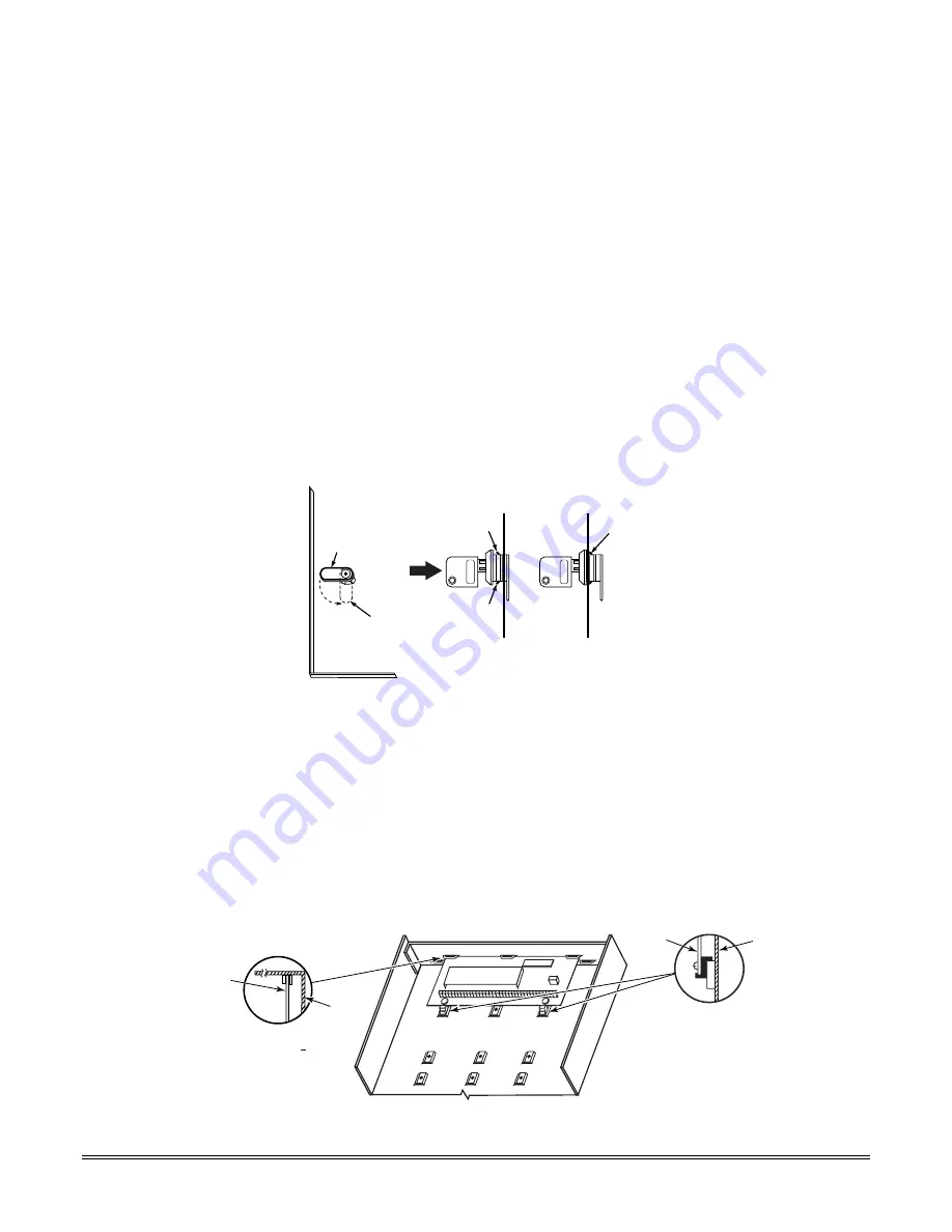
2.  Remove cabinet door, then remove the lock knockout from the door. Insert the key into the lock.  
3.  Position the lock in the hole, making certain that the latch will make contact with the latch 

bracket when the door is closed. When correctly positioned, push the lock until it is held securely 
by its snap tabs. 


Notes 

 The cabinet can be closed and secured without a lock by using 2 screws in the cover's edge. 


CABINET DOOR

BOTTOM

LOCKED

UNLOCKED

cab_loc

k_snap-001-V0

PUSH

SNAP

TAB

SNAP

TAB

PUSH

ON LOCK

UNTIL IT

IS SEATED

SECURELY

STEP 2

STEP 1

CHECK

POSITION


Figure 1. Installing the Cabinet Lock


Mounting the PC Board Alone 

(no RF Receiver) 

1.  Hang two short mounting clips (provided) on the raised cabinet tabs (see Detail B in Fig. 2). 
2.  a.  Insert the top of the circuit board into the slots at the top of the cabinet. Make sure that the 

board rests on the correct row (see Detail A). 


b.  Swing the base of the board into the mounting clips and secure the board to the cabinet with 

the accompanying screws (see Detail B). 


Notes 

 Before installing the cabinet's contents, remove the metal cabinet knockouts required for wiring 

entry. Do not remove the knockouts after the circuit board has been installed. 


+

+

CIRCUIT

BOARD

DETAIL B

SIDE VIEW

OF MOUNTING

CLIPS

DETAIL A

SIDE VIEW

OF BOARD   

SUPPORTING

SLOTS

CIRCUIT

BOARD

ADT3000-013-V0

CABINET

CABINET


Figure 2.  Mounting the PC Board 


Содержание Enterpreneur 3000EN

Страница 1: ...ecurity Systems Security Systems Security Systems Installation and Set Up Guide ARMED READY 1 2 3 4 5 6 7 8 9 0 STAY BYPASS CHIME INSTANT AWAY CODE TEST OFF READY ARMED READY 1 2 3 4 5 6 7 8 9 0 STAY...

Страница 2: ...n the hallway outside may not wake up the sleeper if the door is closed DINING KITCHEN BEDROOM BEDROOM BEDROOM BEDROOM LIVING ROOM BEDROOM BDRM DINING LIVING ROOM TV ROOM KITCHEN BEDROOM BEDROOM TO BR...

Страница 3: ...3 1 About Programming 3 1 Zones and Partitions 3 1 Touchpads 3 2 Wireless Receiver Transmitters and Wireless Keys keyfobs 3 2 Pager Programming 3 2 Function Keys 3 3 Output Devices 3 3 Zone Type Defin...

Страница 4: ...ble and Quick Program Commands 12 1 AVS Command Procedure 12 1 Quick Program Command Results 12 1 System Communication 13 1 Report Code Format Ademco Contact ID 13 1 Uploading Downloading via the Inte...

Страница 5: ...ite maintenance independent of central station monitoring and modification to sites globally via the Internet UL NOTE Uploading Downloading via the Internet has not been evaluated by UL Functions Sing...

Страница 6: ...acid type 12VDC 4AH minimum Long Range Radio Communication Device Primary telephone number messages can be reported via ECP connection to various communication devices check compatibility and availab...

Страница 7: ...et can be closed and secured without a lock by using 2 screws in the cover s edge CABINET DOOR BOTTOM LOCKED UNLOCKED cab_lock_snap 001 V0 PUSH SNAP TAB SNAP TAB PUSH ON LOCK UNTIL IT IS SEATED SECURE...

Страница 8: ...he cabinet into the blocks right hand terminals and tighten the screws Notes Do not mount the cabinet on or near metal objects This will decrease RF range and or block RF transmissions from wireless t...

Страница 9: ...D RED WIRE TO TOUCHPAD GRN WIRE TO TOUCHPAD YEL WIRE pwr_supply 001 V0 Figure 4 Using a Supplementary Power Supply Notes Typical English Display 6150ADT Typical Custom English Display 6160ADT Typical...

Страница 10: ...used Sounder Bell Connections 1 Make sounder connections to alarm output terminals 3 and 4 For supervised output continue with steps 2 and 3 2 Cut the red Bell Supervision Jumper located above termina...

Страница 11: ...ns Notes Use caution when wiring the transformer to the control to guard against blowing the transformer fuse the fuse is non replaceable Wiring to the AC transformer must not exceed 250 feet using 16...

Страница 12: ...panel s auxiliary power and bell output currents are limited as indicated below OUTPUT LIMITATIONS TO MEET CSFM 24 HOUR BATTERY BACKUP REQUIREMENTS AND UL RESIDENTIAL FIRE INSTALLATIONS OUTPUT CURREN...

Страница 13: ...ansceiver 80mA 4219 Zone Expander 30mA 4204 Relay Unit 15 180mA 4229 Zone Expander Relay Unit 30 100mA 4286 Phone Module 300mA If using hardwire devices such as PIRs refer to the specifications for th...

Страница 14: ...ector current draw 4 wire smoke detectors to any zone 2 8 as shown on the next page This control does not automatically reset power to 4 wire smoke detector zones so you must use a relay e g 4204 4229...

Страница 15: ...PE 54 FIRE ZONE RESET 4 WIRE SMOKE OR COMBUSTION DETECTOR N C N O Figure 7a 4 Wire Smoke Detector Using Relay for Power Reset 2000 OHMS EOLR HEAT DETECTOR RED VIOLET AUX PWR 5 _ _ BLK _ 4_wiresmk 008...

Страница 16: ...rol are 2000 ohms Expansion zones have normal response time 300 500 msec except zone connected to each module s loop A which can be set for fast response 10 15 msec 4219 4229 DIP Switch Address Settin...

Страница 17: ...e received within 12 hours If the receiver is mounted remotely Place the RF receiver in a high centrally located area for best reception Do not locate the receiver or transmitters on or near metal obj...

Страница 18: ...at the back of this manual Supervised transmitters send check in signals to the receiver at 70 90 minute intervals If at least one check in message is not received from each transmitter within a 12 h...

Страница 19: ...gnals the keyswitch zone must be programmed to send opening and closing signals a UL commercial burglar alarm installation the keyswitch s tamper switch must be connected in to the alarm system This t...

Страница 20: ...or if the module cover is removed and the tamper jumper is installed Alpha CHECK xx Wire Expansion FAULT xx Wire Expansion ALARM xx Wire Expansion Fixed Glass lxx or 91 if field 199 set for 2 digit di...

Страница 21: ...NC DATA COM 1 3 4 5 6 7 8 KEY 12 AUX DATA COM SYNC GND OUT 17 RED OUT 18 GREEN ORANGE YELLOW BLUE PURPLE BLACK 00 trigcon 015 V0 8 PIN TRIGGER CONNECTOR Notes When using Powerline Carrier devices you...

Страница 22: ...gers using 80 81 Menu modes as you would for any other relay output When using these outputs note pin 1 output number 17 trigger 1 15 ohms to ground when closed output low open when off output high no...

Страница 23: ...e phone module to function even when accessing the system from an on premises phone If you are also using an Audio Alarm Verification AAV unit refer to Audio Alarm Verification AAV section for special...

Страница 24: ...NE TIP RING PLUG DIRECT CONNECT CORD TIP RING GROUND TIP RING GREEN TIP RED RING INCOMING TELCO LINE GREY R BROWN T 4285 4286 TERMINAL ASSIGNMENTS 1 TIP 2 RING PHONE INPUT 3 TIP 4 RING PHONE OUTPUT 5...

Страница 25: ...6 7 and program the zone as zone type 81 56 Menu mode E g Using output 18 for the trigger program an output function in 80 Menu mode as ZT 60 P 0 Action 1 Device 18 ON ON 1 2 3 4 5 6 7 8 1 2 3 4 5 6...

Страница 26: ...CE TRIG GND 12VDC IN SWITCH BANK 2 SWITCH BANK 1 SWITCH BANK 2 SWITCH BANK 1 AUXILIARY AUDIO LEVEL ADJUSTMENT TRIM POT aav_uvcm 004 V1 ZONE TERMINALS OPTIONAL MONITORING ZONE CONNECTION USE ZONE TYPE...

Страница 27: ...se unit board has several terminal blocks for making connections to remote stations telephone lines and to the control panel The AVS ADT base unit connects to the control s ECP terminals with all othe...

Страница 28: ...HEADER RJ31X 1 2 3 4 5 6 7 8 RED BLK GRN YEL RED BLK GRN YEL RED BLK GRN YEL PANEL ECP PHONE AAV TO ALL OTHER ECP DEVICES LED VOLUME ID BUTTON LED NORMAL MODE PROGRAM MODE CALLBACK MODE PANEL TRIGGER...

Страница 29: ...one Lists for relay powerline carrier zones chime night stay cross zone and pager zones 82 Alpha Programming Create alpha descriptors for easy zone identification 29 IP GSM Programming For programming...

Страница 30: ...eless Key Programming Templates section of the 58 Expert Programming mode in Section 5 Zone Programming page 5 6 to program zone information and enroll each button of the wireless keys used Once a wir...

Страница 31: ...provided when the panel is armed in the Instant mode Entry delay 1 is programmable for each partition Exit delay begins whenever the control is armed regardless of the arming mode selected and is ind...

Страница 32: ...tion The check message will automatically disappear from the touchpad dynamically when the zone restores a user code off sequence is not needed to reset the zone Faults of this zone type are independe...

Страница 33: ...e Custom English display touchpad Both partitions must be disarmed POWER UP NOTE firmware version display After powering up AC dI disabled or Busy Standby vx x Dl will be displayed after about 4 secon...

Страница 34: ...onds of power up Table of Device Addresses This Device Uses Address Reports as Enabled By RF Receiver 00 100 56 zone programming input device type entry AUI 1 01 n a automatic if AUI enable field 189...

Страница 35: ...must be 1 if wireless devices are used 23 Quick Forced Bypass 0 no quick forced bypass 1 allow quick bypass code 6 All zones bypassed by this function will be displayed after the bypass is initiated...

Страница 36: ...med in field 33 1 no fire sounder timeout continue sounding until manually turned off This control complies with NFPA requirements for temporal pulse sounding of fire notification appliances Temporal...

Страница 37: ...the PABX entry and set call waiting disable option in field 91 to disable call waiting during control panel calls If the subscriber does not have call waiting and is not using PABX make no entry in th...

Страница 38: ...xceed one minute use zone list 6 to disable dial delay from appropriate zones if necessary SIA Installations delay must be minimum of 15 seconds 53 Misc Fault Delay Time 0 15 secs 6 2 1 2 min 12 8 min...

Страница 39: ...ng the UVS system or AVS system with non ECP connection option 0 must always be used If using the AVS system with ECP connection either option 0 or 1 may be used but note the following IMPORTANT If op...

Страница 40: ...llations and required for residential fire alarm installations 63 Low Bat Report Code 0 no report 1st digit non zero send report Sent when a low battery condition exists in the system s battery UL Req...

Страница 41: ...end report Sent after AC power has been restored after an AC power outage UL Required for UL commercial burglar alarm installations and required for residential fire alarm installations 74 Low Bat Res...

Страница 42: ...nly after Exit Delay expires This option not for use in UL installations 86 Cancel Verify Touchpad Display 0 no 1 yes When enabled 1 yes this feature causes the message ALARM CANCELED to be displayed...

Страница 43: ...call waiting cancel digits must be entered in field 40 PABX Code or Call Waiting Disable and the call waiting disable option must be enabled 1 in entry 2 When selected the system dials the entry in f...

Страница 44: ...r should then call again The phone module will now seize the line and 2 long tones sound followed by the usual voice prompt for the access code If this procedure is not followed phone module operation...

Страница 45: ...0 4 This indicates that the system is reporting an alarm 911 caused by a fault in zone 4 0004 in partition 1 Example 2 Pager displays 1 0 2 2 0 0 5 This indicates that the system is reporting a closi...

Страница 46: ...ions 0 disable all options 1 RF Tamper reports during disarm 2 RF button types send low battery reports 8 RF low battery reports delayed 28 days E g Entering 10 8 2 enables button type transmitters to...

Страница 47: ...e of the codes are suitable choose a code in the reserved range of 750 789 reserved for configurable zone type report codes and make sure to define the code with your central station 184 Configurable...

Страница 48: ...s Display Selects how faults on zones set for this zone type are displayed Power Reset Verification Selects whether the system resets power when user enters code OFF and whether the system performs al...

Страница 49: ...sarmed 3 never show any alarms trbles faults 0 no 4 power reset after fault with code OFF 12 verification see zone type 16 0 no 1 delay 1 2 delay 2 0 no 4 use exit delay 0 no 8 yes see note 2 Entry 7...

Страница 50: ...es TOUCH SCREEN DEVICE NOTE If using more than one touch screen device with the system leave field 197 set to the default value 0 Touch Screen style touchpads automatically display remaining exit time...

Страница 51: ...Programming mode by pressing 56 while in Data Programming mode The following prompts are displayed PROMPT VALID ENTRIES EXPLANATION SET TO CONFIRM 0 NO 1 YES Set to Confirm 0 no 1 yes If 1 Yes is ente...

Страница 52: ...2 09 Fire 22 Disarm 03 Perimeter 10 Interior w Delay 23 No Alarm Resp 04 Interior Follower 12 Monitor Zone 24 Silent Burglary 05 Trouble Day Alarm Night 14 Carbon Monoxide 25 24 Hr Non Alarm 06 24 Hr...

Страница 53: ...number Entry and Loop Number Entry see explanation to continue Used only when enrolling wireless transmitters a Transmit two open close sequences If using a button type transmitter press and release...

Страница 54: ...e serial number will change to 0 s If 0 was entered in error simply re enter the loop number or press and the serial number will return to the display Zn ZT RC In L 10 03 10 RF 1s Summary Screen to co...

Страница 55: ...D to go to prompts for wireless key programming templates A summary screen will appear showing zone 1 s currently programmed or default values Enter the zone number being programmed then press which d...

Страница 56: ...the first prompt after entering 58 was answered Yes To confirm activate the loop input or button that corresponds to this zone The system checks for duplicate If a duplicate exists a long error beep w...

Страница 57: ...PARTITION 1 Partition 1 partition 1 2 partition 2 to continue 6 Enter the partition in which the key is to be active 7 Press to continue ENTER START ZONE 00 QUIT 36 Start Zone Number to continue 8 Th...

Страница 58: ...E Following the successful enrollment of each wireless device remove ONE of the serial number labels from the device and affix it in the appropriate column on the ENROLLED TRANSMITTERS worksheet of th...

Страница 59: ...rt back to the last question to check or change an entry Press to go forward again Output Device programming involves 1 Use 79 Menu Mode to assign module and output numbers and map them to device addr...

Страница 60: ...put Type 0 delete 1 relay on 4204 4229 module 2 Powerline Carrier device to continue Select whether this is a relay or a Powerline Carrier X 10 device If relay is selected skip to B prompt If Powerlin...

Страница 61: ...ch defined function is associated with only one output number This means that if more than one output device needs to perform this particular function you need to define another output function number...

Страница 62: ...umber See below for a list of available zone types CHOICES FOR ZONE TYPES 00 Not Used 05 Trouble Day Alarm Night 14 Carbon Monoxide 01 Ent Exit 1 06 24 Hr Silent 16 Fire w verification 02 Ent Exit 2 0...

Страница 63: ...ut Action 0 6 see list at right Enter the desired device action as listed below Press the key to continue 0 off 4 Change Device State 1 Close for 2 seconds 5 Duration 1 see data field 177 2 Stay Close...

Страница 64: ...3000EN Series Installation Instructions 6 6...

Страница 65: ...l Delay Disable option Zone List 7 See field 93 for Unlimited Reports option Zone List Programming Zone List programming involves 1 Selecting an appropriate zone list number 2 Adding the desired zone...

Страница 66: ...urns to the Zone List No prompt To delete a zone or zones in a zone list enter 1 to continue 01 Zn to Delete 00 Quit 00 Delete the Zone 01 64 zones to be deleted from list followed by to accept each z...

Страница 67: ...partition to continue Enter the partition in which the function key is active Key A Func Zone 95 00 Define Key Function 00 12 see list to right to continue Returns to key number prompt with the next...

Страница 68: ...3000EN Series Installation Instructions 8 2...

Страница 69: ...se words shown in boldface type in the Alpha Vocabulary List The phone module will not provide annunciation of any other words Programming Zone Descriptors Menu Mode 82 Descriptor programming involves...

Страница 70: ...Press 6 to accept the selected word and continue to the next word NOTE If this is the only word you are using for the descriptor press 8 instead of 6 to save that word in memory ZN 01 BACK D OOR Seco...

Страница 71: ...st of letters numbers and symbols on a following page Press followed by the two digit entry for the first letter you would like to display e g 6 5 for A The cursor will then move to the right in posit...

Страница 72: ...6 SENSOR 167 SERVICE 168 SHED 169 SHOCK 170 SHOP 171 SHORT 173 SIDE 174 SKYLIGHT 175 SLIDING 176 SMOKE 178 SONS 179 SOUTH 180 SPRINKLER 182 STATION 184 STORE 185 STORAGE 186 STORY 190 SUPERVISED 191 S...

Страница 73: ...Disarm 07 Display Reminder 10 Display custom words 11 Periodic Test Report 12 Up and About to continue Enter the desired event number for event you want to occur at a specified time Events 10 12 are r...

Страница 74: ...about REPEAT OPTION 0 4 X Repeat Option 0 do not repeat 1 repeat schedule weekly 2 repeat schedule biweekly every other week 3 repeat schedule every third week 4 repeat schedule every fourth week to c...

Страница 75: ...ed key SHIFT functions Those functions shown in diagram above the numerical keys and the right hand functions shown on the ABC keys To perform a SHIFT key function press SHIFT key D key then press the...

Страница 76: ...umber 2 B 2 For entering the number 2 B Used for entering C S ID number 3 C 3 For entering the number 3 C Used for entering C S ID number 4 D 4 For entering the number 4 D Used for entering C S ID num...

Страница 77: ...installer code 0 5 remove all programming options set by 0 3 quick command installer code 0 6 remove all programming options set by 0 4 quick command Quick Program Command Results When either the 03...

Страница 78: ...3000EN Series Installation Instructions 12 2...

Страница 79: ...er or system status number see the following page Ademco Contact ID Reporting takes the following format CCCC CCCCCC Q EEE GG ZZZ where CCCC CCCCCC Customer subscriber ID 4 or 10 digits depending on f...

Страница 80: ...larm 380 Global Trouble Trouble Day Night Canadian panels log and report this code Code Definition 381 RF Sensor Supervision 382 Supervision Auxiliary Wire Zone 383 RF Sensor Tamper 384 RF Sensor Low...

Страница 81: ...allation Site Internet Intranet Communication Module 7720P Programmer Ethernet Network Connection IP compatible Control Panel At the Downloading Office 7810iR ent IP Receiver Internal Router Computer...

Страница 82: ...13 4...

Страница 83: ...can change system master code view event log set system clock program touchpad macro program scheduled events activate output devices triggers relays Partition Master default P1 03 P2 33 same as Mast...

Страница 84: ...only 4 partition master 2 guest Access Group System Partition Master Code 8 user no 2 group 1 8 Factory Assignments none You can assign users to a group then set an access schedule that defines the t...

Страница 85: ...ayed To clear this display simply repeat the disarm sequence enter the security code and press the OFF key again Arming Away Enter code AWAY 2 or simply press appropriate lettered key on the touchpads...

Страница 86: ...cy Fire Emergency B 99 24 hour Audible 24 hour Audible C 96 24 hour Auxiliary IMPORTANT For a Silent panic function if programmed to be of practical value you must program a report code for the zone a...

Страница 87: ...display may occur Some wireless sensors use a non replaceable long life battery which requires replacement of the entire unit at the end of battery life e g 5802 5802CP TELCO FAULT 94 Telephone Line F...

Страница 88: ...3000EN Series Installation Instructions 14 6...

Страница 89: ...windows with contacts should be closed PIRs should be covered use a cloth to mask them temporarily if necessary If a NOT READY message is displayed press to display the faulted zone s Restore faulted...

Страница 90: ...ops zones Any transmitter that is not enrolled will not turn off its zone number Go No Go Test Mode The Go No Go Test verifies adequate RF signal strength from the proposed transmitter location and al...

Страница 91: ...test report sent every 24 hours installer code 0 1 test report sent once per week installer code 0 2 test report sent every 28 days Each mode sets schedule 32 to the selected repeat option the first t...

Страница 92: ...3000EN SERIES INSTALLATION INSTRUCTIONS 15 4...

Страница 93: ...accepts up to 16 transmitters 5883H accepts up to system max transmitters 5800TM Transmitter Module used with 5827BD Wireless 2 Way Touchpad Zone Expansion 4219 WIRED EXPANSION MODULE 4229 WIRED EXPAN...

Страница 94: ...AS RF LOOP 1 INTERNAL SHOCK SENSOR LOOP 2 REED 5819 ENROLL AS RF LOOP 2 REED LOOP 3 TERMINALS LOOP 1 TERMINALS 5800WAVE SET HOUSE ID ENROLL AS RF 5800Micra ENROLL AS RF 5800CO ENROLL AS RF 5801 ENROL...

Страница 95: ...er should be aware that compliance with the above conditions may not prevent degradation of service in some situations Repairs to certified equipment should be coordinated by a representative designat...

Страница 96: ...3000EN SERIES INSTALLATION INSTRUCTIONS 17 2 NOTES...

Страница 97: ...17 3 NOTES...

Страница 98: ...3000EN SERIES INSTALLATION INSTRUCTIONS 17 4 NOTES...

Страница 99: ...rcuits children playing with matches or arson Depending on the nature of the fire and or location of the smoke detectors the detector even if it operates as anticipated may not provide sufficient warn...

Страница 100: ...idity high or low temperatures as well as large swings in temperature may all reduce the actual battery life in a given installation This wireless system however can identify a true low battery situat...

Страница 101: ...umber 4 16 Download Phone Number 4 9 Duplicating Wireless Keys 5 7 Dynamic Signaling Delay 4 4 Dynamic Signaling Priority 4 5 E Earth Ground 2 6 ECP Fail Display 4 16 Enrolling 2 12 5 1 Entering Seria...

Страница 102: ...em Test 13 1 T Tamper Switch 2 13 Telco Line 2 17 Telephone Line Monitoring 1 1 Test Mode 13 1 Test Procedures 13 1 Test Report Code 4 6 Test Restore Report Code 4 7 Touchpad Addresses 2 3 Touchpad Fu...

Страница 103: ...TO PHONE TERMINALS SEE INSTRUCTIONS REMOTE TOUCHPADS EACH PARTITION CAN USE 6150ADT OR 6160ADT TOUCHPADS SEE INSTRUCTIONS PROVIDED WITH TOUCHPAD LOCAL PROGRAMMING MUST BE DONE WITH A 6160ADT BUT NEED...

Страница 104: ...ADT Security Services Inc One Town Center Rd Boca Raton FL 33486 Copyright 2003 K5305V8s K5305V8 11 10 Rev A SIA...

Отзывы: