30
Signal
Connections
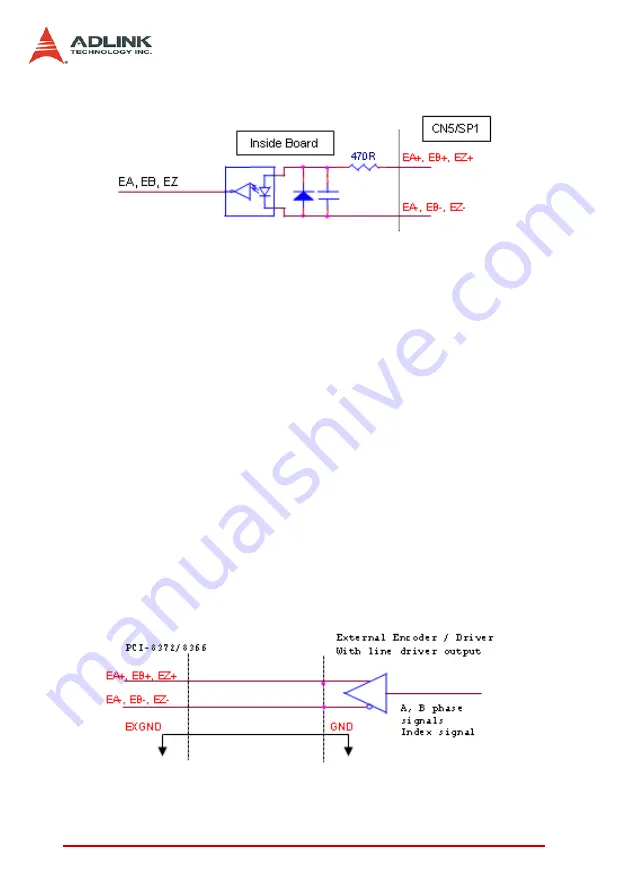
Figure 3-5: Encoder Feedback Signals
Please note that the voltage across each differential pair of
encoder input signals (EA+, EA-), (EB+, EB-) and (EZ+, EZ-)
should be at least 3.5V or higher. Therefore, the output current
must be observed when connecting to the encoder feedback or
motor driver feedback as not to over drive the source. The differ-
ential signal pairs are converted to digital signals EA, EB and EZ
and then fed to the FPGA.
Below are examples of connecting the input signals with an exter-
nal circuit. The input circuit can be connected to an encoder or
motor driver, if it is equipped with: (1) a differential line driver or (2)
an open collector output
Connection to Line Driver Output
To drive the SSCNET board encoder input, the driver output must
provide at least 3.5V across the differential pairs with at least 6 mA
driving capacity. The ground level of the two sides must also be
tied together.
Figure 3-6: Line Drive Output Connection
Содержание PCI-8366+
Страница 4: ......
Страница 14: ...x List of Figures ...
Страница 17: ...Introduction 3 Figure 1 3 Flowchart for Building an Application ...
Страница 26: ...12 Installation 2 2 PCI 8372 8366 Outline Drawing Figure 2 1 PCI 8372 8366 Mechanical Drawing ...
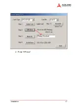
Страница 31: ...Installation 17 2 Press HPI boot ...
Страница 32: ...18 Installation 3 Press Flash DL button and select a kernel4 hex ...
Страница 34: ...20 Installation Figure 2 3 SSCNET Communication Test Utility ...
Страница 49: ...Signal Connections 35 Figure 3 9 Skin Type ...
Страница 144: ...130 Operation Theory ...
Страница 149: ...Motion Creator 135 Figure 5 6 Software Version Information ...
Страница 158: ...144 Motion Creator Figure 5 10 Tuning Window 5 5 1 Component Description Figure 5 11 Trigger Setting Frame ...
Страница 160: ...146 Motion Creator Figure 5 13 Channel Selection Frame Figure 5 14 Motion Frame ...


