Signal Connections
29
3.2
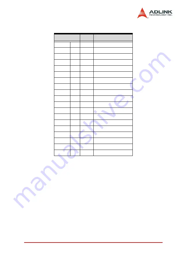
Encoder Feedback Signals: EA, EB and EZ
The encoder feedback signals include EA, EB, and EZ signals.
EA and EB are used for position counting, and EZ is used for zero
position indexing. The input circuit of the EA, EB, and EZ signals
is shown in the diagram below.
Pin No.
Name
Description
CN5
SP1
12
12
EA1+ Encoder A-Phase (+)
13
13
EA1-
Encoder A-Phase (-)
14
14
EB1+ Encoder B-Phase (+)
15
15
EB1-
Encoder B-Phase (-)
16
16
EZ1+ Encoder Z-Phase (+)
17
17
EZ1-
Encoder Z-Phase (-)
46
46
EA2+ Encoder A-Phase (+)
47
47
EA2-
Encoder A-Phase (-)
48
48
EB2+ Encoder B-Phase (+)
49
49
EB2-
Encoder B-Phase (-)
50
50
EZ2+ Encoder Z-Phase (+)
51
51
EZ2-
Encoder Z-Phase (-)
29
--
EA3+ Encoder A-Phase (+)
30
--
EA3-
Encoder A-Phase (-)
31
--
EB3+ Encoder B-Phase (+)
32
--
EB3-
Encoder B-Phase (-)
33
--
EZ3+ Encoder Z-Phase (+)
34
--
EZ3-
Encoder Z-Phase (-)
Table 3-1: Encoder Feedback Signals: EA, EB and EZ
Содержание PCI-8366+
Страница 4: ......
Страница 14: ...x List of Figures ...
Страница 17: ...Introduction 3 Figure 1 3 Flowchart for Building an Application ...
Страница 26: ...12 Installation 2 2 PCI 8372 8366 Outline Drawing Figure 2 1 PCI 8372 8366 Mechanical Drawing ...
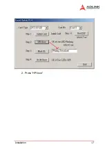
Страница 31: ...Installation 17 2 Press HPI boot ...
Страница 32: ...18 Installation 3 Press Flash DL button and select a kernel4 hex ...
Страница 34: ...20 Installation Figure 2 3 SSCNET Communication Test Utility ...
Страница 49: ...Signal Connections 35 Figure 3 9 Skin Type ...
Страница 144: ...130 Operation Theory ...
Страница 149: ...Motion Creator 135 Figure 5 6 Software Version Information ...
Страница 158: ...144 Motion Creator Figure 5 10 Tuning Window 5 5 1 Component Description Figure 5 11 Trigger Setting Frame ...
Страница 160: ...146 Motion Creator Figure 5 13 Channel Selection Frame Figure 5 14 Motion Frame ...


