SABRE
™
RANGER 5000 User Guide
© 2017 Addvalue Innovation Pte Ltd. All rights reserved.
13
Figure 11
Digital Input and Output; Terminal Data Ready (TDR)
Output; Local Wake up Input
Use Belden cable no. 9535 or similar non-paired shielded cable for these connections.
The number of wires in the cable can vary depending on the user requirements.
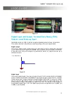
Digital output
There are 4 digital outputs configured as Low side drivers. These outputs are connected
to pin 14(OP1) and pin 15(OP2) of CON801 and pin 2(OP3) and pin 3(OP4) of CON802.
A low side driver will pull the signal to ground when active. An output can sink up to
400mA of current.
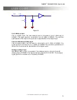
Lo w Side Driver
Figure 12
Digital input
There are 4 digital inputs. They are connected to pin 17 (IP1) and pin 18(IP2) of CON801
and pin 5(IP3) and pin 6(IP4) of CON802. These inputs accept a signal of 0V to +32VDC.
These inputs have a weak pull-down of approximately 300K ohms. A pull-up to +5VDC
may be used to drive these inputs. The input buffer inverts the input logic level. The
minimum input voltage to be declared is higher than, 2.6V. The maximum input voltage to
be declared is lower than, 1.0V. The digital input ground is connected to pin 4 (GND), pin
7(GND) or pin 16(GND).
Low Side Driver


