


7351 Series Digital Multimeter Operation Manual
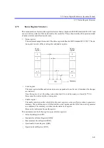
6.7.5 Status Register Structure
6-49
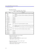
6. Questionable event register
Allocation in the questionable event register is shown in Table 6-8.
Conditions which clear the questionable event register
• When the power is turned on.
• When the *CLS command is executed.
• When the :STATus:QUEStionable[:EVENt]? command is executed.
• When the QSR? command is executed.
Conditions which clear the measurement event enable register
• When the power is turned on.
• When the :STATus:QUEStionable:ENABle 0 command is executed.
• When the QSE0 command is executed.
Table 6-8 Questionable Event Register (QER)
bit
Name
Description
0
Voltage Overload
ON: This bit is set to 1 when OL occurs in the voltage or diode measurement.
1
Current Overload
ON: This bit is set to 1 when OL occurs in the current measurement.
2
Not used
Always 0
3
Not used
Always 0
4
Not used
Always 0
5
Frequency Overload
ON: This bit is set to 1 when OL occurs in the frequency measurement.
6
Not used
Always 0
7
Not used
Always 0
8
Summary of Calibra-
tion
ON: This bit is set 1 when the default calibration values or the calibration values
acquired in previous power ON is used due to the calibration data SUM fail-
ure in the power ON check.
9
Ohms Overload
ON: This bit is set to 1 when OL occurs in the resistance measurement.
10 Not used
Always 0
11 Not used
Always 0
12 Alarm
ON: This bit is set to 1 when an alarm occurs in the measurement.
13 Not used
Always 0
14 Not used
Always 0
15 Not used
Always 0


