7351 Series Digital Multimeter Operation Manual
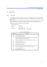
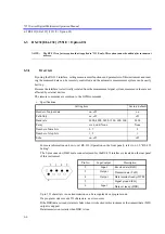
6.3 RS-232[EIA-232] (7351E + Option 03)
6-6
6.3
RS-232[EIA-232] (7351E + Option 03)
NOTE:
The RS-232 is a factory option that is applied to 7351E only. This option cannot be added after instrument
delivery.
6.3.1
Overview
By using the RS-232 interface, setting measurement functions and parameters of this instrument and read-
ing the measured data can be remotely controlled, and the automatic measurement system can be easily
built up.
Because the interface is electrically isolated from the measurement signal system, measured values are not
affected by external devices.
The remote commands are common to the GPIB commands.
•
Specifications
For more information on how to set RS-232 (Operation on the front panel), refer to 6.3.2, “RS-232
Setting“.
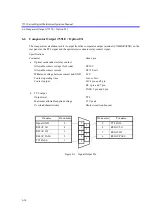
The 9-pin connector (DB-9 male connector) used for the RS-232 interface is located on the rear panel
of this instrument.
Up to 251 characters in one transmission can be recognized as a program code.
If a program code exceeds 251 characters, an error occurs.
If the DSR (data set ready) status is false when it is checked in this instrument, the transmit data (TxD)
output is stopped.
Data transmission restarts when DSR is true.
Setting item
Factory default
Header of output data
on, off
on
Talk-Only
on, off
off
Baud rate
9600, 4800, 2400, 1200, 600, 300
9600
Parity
even, odd, None
None
Number of data bits
8, 7
8
Number of stop bits
1, 2
1
Echo
on, off
off
2
3
4
5
6
Pin No.
Input/output
Description
2
Input
Receive data (RxD)
3
Output
Transmit data (TxD)
4
Output
Data terminal ready (DTR)
5
-
Signal ground (SG)
6
Input
Data set ready (DSR)


