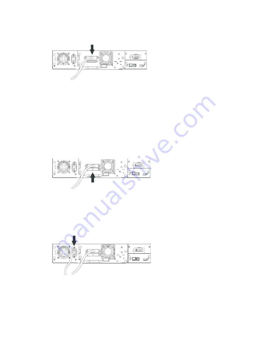
Figure 13
Attaching the SCSI cable to the LTO drive
3.
Attach the other end of the SCSI cable to the connector on the SCSI host bus adapter or to
the connector on the previous device on the SCSI bus.
NOTE:
The host bus adapter should be LVDS. A SE SCSI host bus adapter will work, but will severely
degrade performance, and limit cable length. If there are any SE devices on the same SCSI
bus, the entire SCSI bus will negotiate down to SE speed and severely degrade performance.
Never attach the LTO tape drive to a SE SCSI bus.
4.
Attach the terminator to the remaining SCSI connector on the back panel of the library, if the
library is the last or only device on the SCSI bus (see Figure 14). Otherwise, attach one end
of a SCSI cable to the remaining port and the other end to the next device on the SCSI bus.
Make sure that the last device on the SCSI bus in properly terminated.
Figure 14
Attaching the terminator to the LTO drive
5.
Attach the power cable to the power connector on the back panel of the library (see Figure
15).
6.
Plug the power cable into the nearest properly grounded power outlet.
Figure 15
Attaching the power cable
CAUTION:
To disconnect all power from the library, remove the power cord from the outlet. The
power button only puts the power on stand-by.
7.
Turn on the library using the power button. Check the LCD screen to make sure the library
is receiving power. If it is not, check the power connections and your power source. During
the Power-On-Self-Test (POST), all four LEDs are illuminated briefly, followed by a flashing
Ready LED. When the initialization sequence is complete, the Home screen will be
displayed.
Содержание actiLib Autoloader 2U
Страница 1: ...actiLib Autoloader 2U User and Service Guide Date September 17 2009 ...
Страница 10: ...Figure 63 Releasing the magazine 73 ...
Страница 21: ...Figure 9 Shipping lock before transportation 3 4 5 2 1 ...
Страница 31: ...5 7 OCP Menu Flow Charts Figure 17 OCP User interaction Mode actiLib Library 2U ...
Страница 32: ...Figure 18 Interaction Mode Information ...
Страница 33: ...Figure 19 Interaction Mode Information continuation ...
Страница 34: ...Figure 20 Interaction Mode Commands ...
Страница 35: ...Figure 21 Interaction Mode Configuration ...
Страница 36: ...Figure 22 Interaction Mode Configuration continuation ...
Страница 37: ...Figure 23 Interaction Mode Service ...
Страница 43: ...Figure 28 Slot numbering right magazine ...


