ACES SYSTEMS Viper II Скачать руководство пользователя страница 384


Chapter 22 

Analyzer Management 

(Revision 2.10, Apr 2020) 

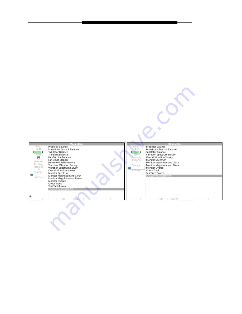
The “Analyzer Management” banner menu screen contains several menu items, three of which 
are used for identification of the analyzer. The other items are user-accessible and editable items. 
All are described in the following sections. 
 

NOTE 

Some options appearing in the following screenshots will not be available on all units as they are 

for development/testing purposes only.  


Viper II 

Cobra II 

Содержание Viper II

Страница 1: ...I Analyzers ACES Systems TEC Aviation Division Document Number 4041 OM 01 Revision 6 00 April 2020 Part Number 10 300 4041 10737 Lexington Drive Knoxville TN 37932 3294 USA Telephone 865 671 2003 Fax...

Страница 2: ...tion purposes TEC makes no warranty of any kind with regard to this material including but not limited to the implied warranties of merchantability and fitness for a particular purpose TEC shall not b...

Страница 3: ...Case 2 9 2 4 4 USB Memory Device 2 9 2 5 Optional Equipment 2 10 2 5 1 USB Keyboard 2 10 3 Using the Gen II Analyzer Rev 2 10 Apr 2020 3 1 Entering Data 3 1 3 1 1 Using the Keys 3 1 3 1 2 Filling in F...

Страница 4: ...7 21 7 2 3 Connect Sensors 7 22 7 2 4 Select Aircraft Condition 7 24 7 2 5 Data Acquisition 7 25 7 2 6 Review Prior Runs Data 7 26 7 2 7 Solution Screens 7 27 7 3 Main Rotor Manage Data Functions 7 31...

Страница 5: ...up 9 3 9 1 2 Sensor Information Screen 9 7 9 1 3 Transient Balance Speeds Screen 9 8 9 1 4 Define Class Wts Screen 9 10 9 1 5 Balance Plane Information Screen 9 13 9 1 6 Label Detail Wt Holes Screen 9...

Страница 6: ...only Rev 2 20 Apr 2020 12 1 Honeywell Performance 12 1 12 1 1 Necessary Equipment 12 1 12 1 2 Analyzer Operation 12 5 12 1 3 Information Screens 12 14 12 2 Manage Jobs 12 17 12 2 1 Review 12 18 12 2...

Страница 7: ...4 23 14 2 Resume Job 14 24 14 3 Manage Jobs 14 25 14 4 Manage Setups 14 25 15 Overall Vibration Survey Rev 4 10 Apr 2020 15 1 Start Job 15 1 15 1 1 Overall Vibration Setup 15 3 15 1 2 Job Identificati...

Страница 8: ...tion 22 11 22 3 3 Analyzer Owner Information 22 12 22 3 4 Battery Information 22 14 22 4 Analyzer Legal Information 22 15 22 4 1 Analyzer Terms and Conditions 22 15 22 4 2 Open Source Components 22 17...

Страница 9: ...ilable Function Keys 24 7 24 3 6 Status Messages 24 8 24 3 7 RPM Warnings 24 8 24 3 8 Multiple Vibration Channels 24 8 24 3 9 Reviewing Polar Charts During and After a Job 24 9 24 3 10 Available Funct...

Страница 10: ...lp you overcome common application difficulties whenever possible For technical support please feel free to contact the home office or complete the online form found at https www acessystems com conta...

Страница 11: ...the TEC factory in any way which may have impaired its safety operation or efficiency or to any product that has been subjected to accidental damage NOTE Annual calibration by TEC or a TEC authorized...

Страница 12: ...d as calibrated by a sticker stating the date of calibration and next due date of calibration A certificate of calibration will be provided to you to verify compliance to inspectors A permanent record...

Страница 13: ...ison Analyzer Versions Analyzer Functions Cobra II Viper II Propeller Balance Main Rotor Track Balance Tail Rotor Balance Transient Balance Fan Turbine Balance Fan Blade Mapper Honeywell Performance w...

Страница 14: ...manual for details on creating reports The analyzer also has a USB port to allow you to transfer the vibration survey spectra and balance reports directly to a USB flash drive for storage review or p...

Страница 15: ...functions to rapidly configure the analyzer based on the information contained in the Setup The term Job as used in this manual means the stored Setup information plus the collected balance vibration...

Страница 16: ...Tracker as used in this manual refers to the ACES Systems Model 550 TraXTM The term Forward Looking Aft abbreviated as FLA with regard to the perspective used to orient equipment during the setup or...

Страница 17: ...l 2020 This chapter gives you a brief tour of the analyzer It describes the various keys and their functions the input and output ports and the standard accessories supplied with the analyzer Optional...

Страница 18: ...will remain constant There is an additional Power off Timeout feature available that will power the analyzer off completely after a period of inactivity This feature is also described in Chapter 22 Th...

Страница 19: ...ay between Day and Night mode Day mode is enabled by default and makes the screen easier to see in daylight conditions Night mode is designed to increase the contrast between the background and text o...

Страница 20: ...apidly and then stop for two seconds The letter N should appear on the screen The BACKSPACE key is used to clear input in the current field When only the cursor is displayed this key will delete only...

Страница 21: ...TFT display is how the analyzer communicates with the user The screen displays messages menus selection lists graphic illustrations and survey plots The display has an LED backlight with adjustable b...

Страница 22: ...as the input for a single plane balance job The six pin connector enables the analyzer to provide sensor power as required to the sensor being used 2 3 1 2 TACH Ports The TACH inputs are three pin fem...

Страница 23: ...ional input output ports are provided on the left panel of the analyzer They are the 18 28V DC IN and STRB JEDA ACCY Viper II or STRB ACCY Cobra II not pictured ports STRB JEDA ACCY 18 28V DC IN 2 3 2...

Страница 24: ...These ports can accept standard USB peripherals such as USB Memory Devices and Wired USB Keyboards It is designed to work with accessories with a direct wired connection between the analyzer and the...

Страница 25: ...ase with a mild soap solution and coat with an ARMOR ALL type protectant to preserve appearance ARMOR ALL is a registered trademark of the Clorox Company The case is designed to be airtight with the i...

Страница 26: ...this application many accessories are available that are too numerous to list concisely in this manual 2 5 1 USB Keyboard A USB Keyboard can be used to speed entry of data into the analyzer To use si...

Страница 27: ...w keys to place the cursor in the desired field Press the key one time and the first character of the key should appear in the active field To generate the second character on a multi character key pr...

Страница 28: ...described in the previous section If you wish to change text already in place in these fields place the cursor in the field you wish to change then press the BACKSPACE key once for each character in t...

Страница 29: ...ick on the Technical Library link as shown below In the Technical Library page you may use the Filter Results drop down lists Simply click on the Bold Type headers and click in the checkbox es to narr...

Страница 30: ...op up menu you can select the Save button and the E Setup will be saved in your Downloads folder by default Alternatively you can click the down arrow on the right side of the Save button and select S...

Страница 31: ...lyzer and insert it into a USB port on the computer When the device opens select the aces_export folder from the memory stick and open it Copy the necessary setup and paste a copy into the aces_setups...

Страница 32: ...Management menu select Database Management Select Import Setups from USB Drive and press OK If an existing setup with the same name as the setup you are importing exists you will be asked if it is ok...

Страница 33: ...n the analyzer is turned on See the following figure From this menu you may access all functions of the analyzer by using the available menu choices Chapters 4 through 22 of this manual describes each...

Страница 34: ...t hand portion of the display is separated from the majority of the display with a line The screen to the left of this line is reserved to display various status messages describing different states o...

Страница 35: ...within a Main Menu Job function displays the Incomplete Jobs list Only jobs that are left unfinished will appear in the list and will be preceded by an I inside a box Using the key highlight the job y...

Страница 36: ...apter 3 Revision 2 10 April 20 3 4 3 Manage Jobs Selecting Manage Jobs from within a Main Menu Job function presents several sub menu choices as shown below These choices allow you to manage previousl...

Страница 37: ...n screen viewing Incomplete jobs will be preceded by an I inside a square When viewing is complete press the F0 Back Up key to exit the screen The analyzer will then return you to the Manage Jobs menu...

Страница 38: ...the report the page number and status bar will update After the report is created the screen will change to indicate that the process is complete Also the left hand side of the screen Pending Reports...

Страница 39: ...ending reports which will be transferred to the USB memory device then stored in the aces_reports folder of the USB memory device Whenever reports are pending the F1 Xfer Rpt button is visible as show...

Страница 40: ...move the USB memory device to a computer you can open or print the reports on the computer without the need for any additional software provided the computer has a PDF reader installed The reports wi...

Страница 41: ...t be presented with a list of available jobs After selecting the job you want to delete or when selecting to Delete All jobs you will be asked to confirm your selection Press either F1 Yes to continue...

Страница 42: ...cting the Export option presents a list of stored jobs on the Export Job to USB banner screen From the list you may choose a job to be exported directly to a USB flash drive The exported job file is s...

Страница 43: ...ng the Gen II Analyzer Chapter 3 Revision 2 10 April 20 When the export is complete the screen will display the Operation Complete message Press the F5 Continue key to return to the Export Job to USB...

Страница 44: ...stored in the analyzer 3 4 4 1 Edit Selecting the Edit function displays the Setup List screen Select the setup you wish to edit and press OK The Edit Setup screen will be displayed giving you three o...

Страница 45: ...job function Setup screen Edit the setup as necessary and press OK to store and exit the edited setup screen Refer to the applicable paragraph in Chapters 4 through 15 for detailed instructions on ho...

Страница 46: ...report creation is complete the message Report created will appear In addition the Pending Reports value will increase by one indicating there is another report ready for transfer to the USB flash dr...

Страница 47: ...l setup for deletion After making your selection you will be asked to verify your intent to delete the selected setup by pressing the F1 key for Yes or the F5 key for No NOTE We highly recommend you c...

Страница 48: ...xported directly to a USB flash drive The exported setup file is saved in a tgz format and can be uploaded into another analyzer or used to aid ACES Product Support when assisting customers When the e...

Страница 49: ...it is strongly recommended that you format them with a FAT32 file system as described in Chapter 22 Analyzer Management The files located on your USB flash drive will vary but can include those folder...

Страница 50: ...cation contains jobs that you want to import into the analyzer s memory You will manually copy files into this location for later import Files can be obtained from another analyzer or a previous expor...

Страница 51: ...on matches the analyzer and serial number into which the USB flash drive is plugged the menu items described in the license file will become active and visible on the analyzer s Main Menu To purchase...

Страница 52: ...wn below Each of the listings on this banner screen menu is an option within the function Descriptions of each of these options follow along with the information required to complete the menu screens...

Страница 53: ...operation 991D 1 Accelerometer Although the Gen II analyzers will support a full range of vibration sensors the 991D 1 accelerometer see the illustration below was selected as the standard for use wit...

Страница 54: ...Phototach an ACES Systems LASETACH or an interface for optional speed sensors such as a magnetic pickup or pulse generator The cable is a three wire shielded cable insulated in a bright yellow petrole...

Страница 55: ...to the vibration sensor or reflective tape both methods are described in more detail below Using the Propeller Protractor For correct use of the protractor when measuring relative to the vibration sen...

Страница 56: ...opposed engine Attach the adapter nut end to the exposed case bolt threads then slide the right angle mount over the stud end and secure with the supplied nut Two sets of the adapters are required fo...

Страница 57: ...performance under varied operating conditions Using a lower quality tape will cause inaccurate tachometer readings or unreliable phase information The tape is manufactured by the 3M Company and is th...

Страница 58: ...ting a new job with no setups previously defined in the analyzer s memory 2 starting a new job with previously defined setups available in the analyzer s memory or 3 resuming an incomplete job being h...

Страница 59: ...he actual setup names will be those which you have entered into your analyzer If you are resuming an incomplete job being held in the analyzer s memory the opportunity to do so is presented immediatel...

Страница 60: ...data 4 1 1 1 Propeller Balance Setup Screen To complete the Prop Balance Setup banner screen as shown below do the following 4 1 1 1 1 In the Name field enter a name for this setup using the keypad R...

Страница 61: ...ned locations or holes where trim balance weights can be added If you select Yes a page for defining the angle of each hole will be provided The No answer indicates that no predetermined locations are...

Страница 62: ...as viewed standing Forward of the propeller Looking Aft FLA toward the tail of the airplane 4 1 1 1 14 Using the key move to the Tach Type field Using the key select the type of tachometer you are us...

Страница 63: ...D according to which of the analyzer s input channels you intend to use The default for single sensor input is Channel A Use the key to make the selection If you are conducting a two sensor balance ch...

Страница 64: ...all fields set at 0 and press the F0 Back Up key This sets the ICF at the default for the known conditions The ICF default value is added automatically when the Setup is created The user may press thi...

Страница 65: ...e the F3 key Pressing the F3 key will display additional function key options giving you the option to press F1 Avg Def to set the averaged ICF to the default ICF pressing F2 Def by HP to return the I...

Страница 66: ...is setup in paragraph 4 1 1 1 199 above 4 1 1 3 1 This is an information only screen for use in verifying the parameters of the vibration sensor you have chosen You may not edit or otherwise enter inf...

Страница 67: ...ollowing 4 1 1 4 2 Use the key to move to the No of Holes field Enter the number of holes that correspond to the total number of trim weight mounting locations The valid range of values for this field...

Страница 68: ...hole number 1 as viewed from the front of the engine looking aft To determine this angle do the following With mag switches OFF rotate the propeller so the tachometer triggering device magnetic inter...

Страница 69: ...of each hole number and record that angle adjacent to the hole number See the example Prop Hole Layout Setup screen shown at the beginning of the section For example if the number 1 hole is near the 6...

Страница 70: ...Depending on whether or not you made use of predetermined hole locations you may have also defined values for a number of trim weight mounting holes If these steps have been completed then the Job Ide...

Страница 71: ...ormation screen will be displayed Information on this screen is optional but will appear on the job report if entered The function keys across the bottom of the screen will appear after an entry in a...

Страница 72: ...target blade will produce the best results Connect the tachometer cable to the Phototach connector Route the cable away from hot areas and electrical equipment back to the cockpit and attach to the t...

Страница 73: ...tach illuminate and extinguish as the tape crosses the beam This indicates the position of the tape is correct Remove the tape backing and attach the reflective tape to the propeller at that location...

Страница 74: ...anner screen shown above with the statement to Perform a FOD check and start engine s per flight manual Start the engines and establish normal operating conditions When normal operating conditions are...

Страница 75: ...the values outlined in Chapter 24 paragraph 24 2 5 RPM Warnings Once you have reached your target RPM press OK to continue The screen changes to display the Run x banner screen See the figure below T...

Страница 76: ...r when a minimum number of consistent samples have been collected and it is ok to stop data acquisition If you are conducting a two 2 engine balance this process will be repeated for the second engine...

Страница 77: ...3 Retake All key if balancing two engines This option returns you to the Set Engine Speed banner screen see paragraph 4 1 6 above The data can be viewed in a polar chart format by pressing the F4 Pola...

Страница 78: ...n on for the data collection phase of the job on the first run This option will only be available if Holes field was selected to Yes If the previous trim balance weights were left on press the F1 Yes...

Страница 79: ...alance Solution banner screen will be displayed as described in paragraph 4 1 8 1 below If the Holes field was set to Yes the Prop Suggested Installed Weights banner screen will be displayed as descri...

Страница 80: ...installed weight be totally replaced In some cases this may mean removing and reapplying weight at the same or near the same location Failure to remove previously installed weight prior to applying th...

Страница 81: ...e on each side of the 270 degree location and enter them in the two fields Use the key to move between the fields Press OK to continue The screen displays the Record Split Weights banner screen like t...

Страница 82: ...ed and Installed In the example screen shown above the Suggested solution is 20 4 180 which means the analyzer suggests 20 4 grams g of weight at 180 degrees from the index point see Page 4 4 on how t...

Страница 83: ...ious run must be removed The remove weight message will be repeated for every run and solution Each new solution dictates that the previously applied solution installed weight be totally replaced In s...

Страница 84: ...w you to complete 6 runs in attempts to balance If the balance job is not completed by the sixth run you should suspect possible problems with your technique or mechanical faults with the engine and o...

Страница 85: ...when balancing without predetermined hole locations as explained in Paragraph 4 5 below The selection field below the Current Vibration line allows you to use the or keys to select a next action for...

Страница 86: ...ume Job The features in this section are common among all jobs Because of this they are contained in Chapter 3 Using the Gen II Analyzer 4 3 Manage Jobs The features in this section are common among a...

Страница 87: ...use of this they are contained in Chapter 3 Using the Gen II Analyzer 4 5 Weight Calculator CAUTION If test weights were used on the spinner they must be removed before installing any permanent weight...

Страница 88: ...t of pressing the Wt Calc key on the Vibration Summary screen In the Solution Angle line enter the angle of the installed test weight Use the same method that you used for placing the test weight This...

Страница 89: ...ion solution in this case 80 Grams 189 degrees is displayed at the top of the screen The next line states Enter New Location Use the keypad to complete the next two fields Angle 1 and Angle 2 Locate t...

Страница 90: ...ew Main Polar view explanation in Chapter 24 Lucas 2 17 2016 2 00 Major rewrite generalizing the manual to cover both the Viper II and Cobra II This chapter was updated with screenshots and correction...

Страница 91: ...Chapter 5 RESERVED Revision 1 00 Dec 2014...

Страница 92: ...Chapter 6 RESERVED Revision 1 00 Dec 2014...

Страница 93: ...t by looking at each of the chart forms found in the main rotor section then by using these forms to create an actual setup 7 1 Main Rotor Setup This section covers the complete setup process in the G...

Страница 94: ...analyzer The value selected for this field determines which analyzer channel will be used to measure and display the vertical vibration 7 1 1 3 Use the key to move to the Lateral Chan field Use the ke...

Страница 95: ...ill allow data collection at less than the RPM chosen in the setup Example This feature would be set to NO when an aircraft requires data collection at both 70 NR and 102 NR 7 1 1 12 Press the key and...

Страница 96: ...device specific instructions can be found in the Model 550 TraXTM Operational Supplement ACES P N 75 900 4043 7 1 2 1 In the Rotor Diameter block use the keypad to enter a number between 1 00 and 999...

Страница 97: ...ber between 30 and 90 degrees 7 1 2 7 Tracking Planes information is only visible if four or more even number blades are selected in the Main Rotor Setup page This field is used to designate the numbe...

Страница 98: ...r is entered in an ID field the setup will require an electronic chart be defined and will result in corrections being given for that measurement vs condition o If the same ID number is given to more...

Страница 99: ...alyzer to present solutions Track splits must be 0 25 inches 6 35mm or greater for the analyzer to present a solution 7 1 3 1 Conditions Setup Screen Example 2 In the example main rotor condition setu...

Страница 100: ...ed on this average The recorded track split for FLT 80 and FLT 120 will also be averaged with a second solution based on this average This is an example of a setup for use on an aircraft that requires...

Страница 101: ...ach of the movement types Weight Weight adjustments should always be entered as the addition of weight Sweep Select FWD or AFT for the direction of blade movement if adjusting lateral balance using sw...

Страница 102: ...2 3 2 Analyzer Version Information When completed press OK 7 1 5 Chart Definition The final step in the setup process is to define the electronic chart forms as described in paragraph 7 7 below Analyz...

Страница 103: ...Gen II User Manual 7 11 Main Rotor Track Balance Chapter 7 Revision 3 00 Apr 2020 Rotor diameter 37 0 Feet Lead lag units are read in inches Rotor speed 385 RPM...

Страница 104: ...hannel B The type of vibration sensor chosen for this setup is the 991D 1 The type of tachometer source for this setup is the Mag P U The tachometer channel for this setup is channel 1 Number of weigh...

Страница 105: ...bration will be measured and recorded for this setup Press OK to proceed to the next screen 7 1 6 2 Tracking Setup Screen Enter 37 00 in the first block using the keypad Select ft for units of rotor d...

Страница 106: ...and FLT120 One lateral chart has been identified for the lateral measurement in Hover only The vibration Target for Vertical measurements has been set at 0 20 IPS for Ground and Hover and set at 0 10...

Страница 107: ...e FWD moving a blade UP using either pitch change links or tabs The solution logic has been set to MAX and will present the solution related to the highest vibration readings attained for the vertical...

Страница 108: ...left as None Max ICF Update is 50 Rotation is 45 degrees The type of adjustment applied in accordance with this chart is pitch change link in flats therefore FLT has been entered The influence co effi...

Страница 109: ...e The chart type is Regular This chart uses no sweep adjustments and is therefore left as No No Adjustment Blade Pos is left as None Max ICF Update is 50 Rotation is 45 degrees The type of adjustment...

Страница 110: ...e a sweep adjustment for balancing it is not the only type of adjustment used and therefore requires this entry to be left set as No No Adjustment Blade Pos is left as None Max ICF Update is 50 Rotati...

Страница 111: ...s adjustment per 1 0 IPS vibration The Move line for this position is 5 30 When completed press OK to save and exit this setup 7 2 Main Rotor Balance Process The following paragraphs present the main...

Страница 112: ...ining a setup If you have previously saved setups stored in the analyzer s memory a screen displaying the list of setups will be displayed You can then select a setup from this list to use for the job...

Страница 113: ...OK If the setup you need is not present press the F1 New key to proceed to the Main Rotor Setup screen to define a new setup Use the F2 key to view detailed information about the setup Job Identificat...

Страница 114: ...use the vibration sensor installation locations as specified by the applicable polar charts The orientation of the sensor is key to the accuracy of the chart if the sensor is installed in a direction...

Страница 115: ...the vibration results from the first applied correction While still in the Connect Sensors banner screen a message is presented near the bottom that reads Tach Power is On The Block directly below thi...

Страница 116: ...the current run and direct you to shut down the aircraft 0 If during the current run the F2 Adjust key becomes visible the analyzer has collected enough information to present a solution The solution...

Страница 117: ...high When the amplitude reaches a lower level Approx 0 05 IPS the error value may remain high This is a normal response and is not cause for alarm Press the F1 Reset key to restart the measurement an...

Страница 118: ...rent run Always observe the run number and condition name at top of the screen to identify the data you are viewing This screen also offers a chance to retake the measurements Press the F1 Retake All...

Страница 119: ...ext solution will be the best course of action The analyzer will present all of the solutions that are possible from the data gathered for the current run This means that it is possible for the analyz...

Страница 120: ...e applied is LFL or Lateral Flats of a damper sweep The line at the bottom of the screen serves as a reminder that a positive suggested solution equals adding weight Sweep Aft Blade pitch link up and...

Страница 121: ...close the job and not allow resuming at a later time If you wish to stop the job temporarily press the Main Menu key or simply turn the analyzer off When you have finished entering the adjustments per...

Страница 122: ...esponsibility to adjust the amount either up or down to achieve a quantifiable adjustment Remember that the analyzer will update the influence co efficient between every run based on the vibration res...

Страница 123: ...efficient for the job The following paragraphs will describe these new screens and how to navigate through them to review this information 7 3 1 Main Rotor Review Job Upon selecting to review a job th...

Страница 124: ...itional navigation instructions for the Polar Chart view 7 3 2 View Main Rotor Track and Balance The View Main Rotor Track and Balance screen appears as shown above This screen presents both the sugge...

Страница 125: ...ment ratio of each blade position Pressing the or keys will toggle between multiple chart types if more than one is defined for the setup Press the F1 key to ViewMeas and return to paragraph 7 3 1 Pre...

Страница 126: ...hart ICFs screen shows how the influence coefficient magnitude and rotation was changed as a result of the correction made on each run Because the analyzer continues to learn between runs it is very i...

Страница 127: ...Resume Job The features in this section are common among all jobs Because of this they are contained in Chapter 3 Using the Gen II Analyzer 7 5 Manage Jobs The features in this section are common amo...

Страница 128: ...ggle between Regular and Irregular in the Chart Type field then pressing the key to move to the next field The remaining fields in the screen will automatically change if necessary The tracking influe...

Страница 129: ...eight positions have the same ICF and type of adjustment and all move lines are equally spaced around the chart Using this chart follow the example below to properly define a Regular main rotor chart...

Страница 130: ...to be placed in the setup Adj Unit Using the keypad enter a three letter designator for the type of adjustment utilized by the chart In this case PLT has been entered to represent plates The designat...

Страница 131: ...rotor balance chart shown to the right presents two different types of adjustments the addition of weight to target or blank and sweeping either the target or blank blade aft The ICF is different for...

Страница 132: ...uses 45 degrees With 45 degrees selected any move line that falls more than 45 degrees outside of the expected vector for a given adjustment and the analyzer will not update the ICF Using the keypad e...

Страница 133: ...used to move a blade 1 0 unit of measure at the condition listed Conditions The condition name will be automatically entered and is not editable Adjustment Name Using the keypad enter a three characte...

Страница 134: ...a particular blade during a track and balance job An optimized solution is provided by the analyzer that requires no adjustments to the designated No Adjustment Blade Press OK to save the setup Revis...

Страница 135: ...ach of the chart forms found in the tail rotor section then by using these forms to create an actual setup 8 1 Tail Rotor Setup The following paragraphs illustrate each of the screens necessary to def...

Страница 136: ...using the key Press the key to move to the Tach Position field Using the key select the tachometer position in hours for the majority of aircraft enter 12 o clock regardless of the actual clock positi...

Страница 137: ...y be used for balancing the tail rotor you may enter it in this block This is the total amount of balance weight allowable not the limit of each balance position If the Installed Weights for a single...

Страница 138: ...ion as 5 0 grams adjustment per 1 0 IPS vibration and the move line of 10 00 using the keypad Press the key and enter the third weight position name of BLANK Using the key to change fields enter the i...

Страница 139: ...tlined in paragraph 8 1 1 to complete the Tail Rotor Setup screen as shown in the screenshot above When finished with the main setup screen press OK 8 2 2 Tail Rotor Condition Setup Screen The name fo...

Страница 140: ...g names and chart IDs until all conditions are defined Press the key and if there is more than one chart ID specified the Soln toggle field will appear The three choices are All Max and LSQ Least Mean...

Страница 141: ...A B Target The Tail Rotor Chart Setup screen for the first condition 80 appears next Using the tail rotor polar chart above fill in the appropriate information as follows The name for the chart 80 ha...

Страница 142: ...ARGET blade as 12 00 Press the key and enter the second weight position name of A Press the key and enter the Add move line for weight placement on the A blade as 3 00 Press the key and enter the next...

Страница 143: ...key and enter the number of weight positions using the keypad This example uses 4 weight positions Press the key to enter the grams per IPS influence for the tail rotor This example uses 100 00 grams...

Страница 144: ...he user with the data acquisition and correction capabilities of the Gen II analyzers Prior to starting a new tail rotor balance job you must first select the Tail Rotor Balance option from the main m...

Страница 145: ...analyzer will present a message prompting you to verify that you wish to finish the incomplete job or begin a new job The screen will display the message The last job performed is incomplete Do you wa...

Страница 146: ...nformation is optional but it is suggested that at least a customer name be entered as it will aid in identifying the job for future use If the analyzer has been used previously a list of customer nam...

Страница 147: ...o the accuracy of the chart If the sensor is installed in a direction other than that specified the phase clock angle will be incorrect and any solution will not be accurate Tach Power need not be ON...

Страница 148: ...uire data This screen will only appear in Multiple Condition balance runs In a single condition run the next screen to appear is the Data Acquisition screen proceed to paragraph 8 3 7 Use the key to h...

Страница 149: ...long as the error continues to decrease This will insure you have the most accurate data possible Use the OK key to exit this screen and store the reading The text below the Current heading indicates...

Страница 150: ...has been collected at all of the conditions the condition boxes will have X s showing that data has been collected After data has been collected press the F1 End Run key to review the prior measureme...

Страница 151: ...nished reviewing press OK to continue to the solution process 8 3 9 Shut Down Engines A screen directing you to shut down the engine s will appear next You can use the F0 Back Up key to return to the...

Страница 152: ...t is extremely important that these changes are entered as they will be used to update the influence co efficient for the next run Use the keypad to enter changes If weight is removed from a location...

Страница 153: ...e tail rotor or the suggested weights are smaller than the minimum hole weight For instance in the example below the attaching nut and bolt weigh 3 9 grams This is larger than either of the suggested...

Страница 154: ...eigh 3 9 grams To re solve the solution simply compensating for the minimum hole weight press OK to display the new solution If there are existing weights on the tail rotor continue below to obtain th...

Страница 155: ...ow Run 1 Suggestion will be the minimum weight required in the minimum number of holes allowing for the attaching hardware These weights may not be in adjacent holes This is necessary to provide the w...

Страница 156: ...d with the Balance Status screen shown below Press F1 Quit Job to mark the job as complete without the option for resuming the job at a later time Pressing F1 will return you to the Main Menu Choosing...

Страница 157: ...gested as well as the installed corrections to the rotor To view a different run number press the or keys To view the chart information for the job press the F1 Chart key and refer to paragraph 8 4 2...

Страница 158: ...Any additional charts will have similar screens to view Pressing F5 Continue will progress through all available screens for all conditions When returned to the View T R Balance screen paragraph 8 4...

Страница 159: ...age Jobs The features in this section are common among all jobs Because of this they are contained in Chapter 3 Using the Gen II Analyzer 8 7 Manage Setups The features in this section are common amon...

Страница 160: ...ns spaced equally around the chart all adjustments are of the same type and all adjustments carry the same ICF The next paragraph details the process for defining a tail rotor Regular chart setup Regu...

Страница 161: ...the chart uses an adjustment type such as the number of washers per IPS simply enter this number and overlook the label of grams WtPos Add The lower portion of the screen provides fields for entry of...

Страница 162: ...arget and Blank have an ICF of 10 grams per 1 0 IPS where A and B have an ICF of 33 grams per 1 0 IPS The clock angle move lines are not equally spaced around the chart therefore it must use the Irreg...

Страница 163: ...s the key to move to the Add field Enter the clock angle move line for this point For the TARGET weight position the move line is 6 00 Perform this for each adjustment point shown on the chart to comp...

Страница 164: ...on Descriptions of each of these options follow along with the information required to complete the menu screens within the options and the steps necessary to perform the balance function 9 1 Create S...

Страница 165: ...o resume it Pressing the F1 Yes key will return you to the last logical in progress step of the job Pressing the F5 No key will proceed as described in the two examples below depending on your circums...

Страница 166: ...he Transient Balance Setup banner screen shown below See paragraph 9 1 1 below for step by step instructions on completing the Transient Balance Setup 9 1 1 Transient Balance Setup 9 1 1 1 The Transie...

Страница 167: ...e you choose will aid you in differentiating this setup from other stored setups should you choose to use or review it at a later time The name should be one of your choosing which will be easily reco...

Страница 168: ...rather than a specific class weight by name 9 1 1 9 If you selected Class or Both in the Balance Wt Type field the Num Class Wt Sets field will be available Using the key move to the Num Class Wt Set...

Страница 169: ...vibration measurements 9 1 1 14 Move to the Min Baln RPM minimum balancing speed field by using the key Enter the minimum speed in RPM that may be used for this balance setup The value entered here m...

Страница 170: ...Phototach and Lasetach The available selections are Optical Mag P U Mod Tth and Adj Tth If AdjTth is selected the additional Delta field will appear after Tach Pos FLA See paragraph 9 1 2 5 below for...

Страница 171: ...xt field 9 1 2 9 Use the key to select the Sensor Type you will use for this balance If the sensor you intend to use is not among those listed see Chapter 22 Analyzer Management to learn more about ad...

Страница 172: ...choose between Accel Decel or Both 9 1 3 3 If Both is selected in the Acquire on field the Order field will be displayed Use the key to move to this field This field allows you to choose the order in...

Страница 173: ...a known speed range where vibration data should not be considered for calculating a balance solution Selecting Yes will remove the Bins and Target fields for the affected speed band 9 1 3 8 Press the...

Страница 174: ...he first and second weight You will have the option to accept the recommended setting or to ignore it 9 1 4 3 Use the key to move to the Num Wts number of weights field Use the numeric keypad to enter...

Страница 175: ...adjacent Name field The unit of measure is that which you defined in paragraph 9 1 1 11 above Typically the first entry in this table will be a NULL or NO WT weight A Null weight is one that may be us...

Страница 176: ...efined only one balance plane you will only complete one Balance Plane Information screen 9 1 5 2 Use the key to move to the Posn Type field This field will define the terminology used to refer to the...

Страница 177: ...ail weights For example with this field set to Yes if there are 15 Usable holes and four are already filled with detail weights the analyzer will only place trim balance weights in 11 With this field...

Страница 178: ...orward out of the intake 9 1 5 12 Use the key to move to the MaxWt Position maximum weight per position field Enter a numeric value to define the maximum total number of grams or ounces as defined in...

Страница 179: ...nd its triggering device magnetic interrupter reflective tape etc With the fan in this position use the 12 00 position as the 0 or 360 degrees index point and measure opposite the direction of rotatio...

Страница 180: ...osition the angle may be measured as 15 degrees On the screen use the keypad to enter the angle of position 1 as 15 Then using the key to move to the adjacent field No input the number 1 Next measure...

Страница 181: ...influence coefficient 9 1 7 3 The All Sensors Use the Same ICF field is only available if multiple sensors were selected in paragraph 9 1 1 12 above Use the to toggle the YES NO answer field to indic...

Страница 182: ...9 1 7 9 The Deg field identifies the phase correction in degrees If no known ICFs are available leave this field at the default value of 0 This field will be updated upon executing the Quit Job selec...

Страница 183: ...field as necessary using the analyzer keypad If Engine Serial Numbers have previously been entered in this analyzer you may optionally press the F3 Eng S N key and select a serial number from the sto...

Страница 184: ...the optical tach Before starting the engine make sure all previously installed trim balance weights have been removed On some engines there may be detail or factory installed weights which must not be...

Страница 185: ...ke any minor adjustments as necessary and then press OK to continue Use the F3 Pol key to reverse the polarity of the Tach Signal If the Current RPM is erratic at a stable engine speed press this key...

Страница 186: ...If a speed exclusion zone was configured in paragraph 9 1 3 7 the message Entering Speed Exclusion Zone SEZ will be displayed as well as a yellow box across the ribbon gauge with the letters SEZ see t...

Страница 187: ...retake only the Acceleration data F2 RetakeDec Allows the user to retake only the Deceleration data F3 RetakeAll Allows the user to retake all data F4 Plot Displays a vibration plot as shown in parag...

Страница 188: ...ultiple sensors and multiple speed bands in both an Acceleration and Deceleration run The function keys available are F0 Backup Returns to the Review Prior Run s Data screen shown in 9 2 5 4 F1 Retake...

Страница 189: ...his may require the removal of that weight for verification Select F5 No if the weights were already removed or there were no existing weights installed 9 2 5 8 List Run 1 Existing Weights From this s...

Страница 190: ...the existing weight and location information entered in the previous screen 9 2 5 10 If this is the first suggested weight screen the weights will be test weights unless an established influence was e...

Страница 191: ...olumn with a heading of Suggest is the Class Weight suggested for that Position The right column with a heading of Install is the entry for the actual Class Weight installed in a particular Position T...

Страница 192: ...to identify missing weights from the class weight set currently being used Use the or keys to move from weight to weight When you reach a weight that is not available use the and keys to place an X i...

Страница 193: ...e this job without the option to resume at a later time The Quit Job selection will update the influence coefficient in the setup for use in follow on Jobs F6 Graph Displays a graph of the balance pla...

Страница 194: ...setup 9 2 6 2 When the vibration levels have been reduced to a level equal to or lower than the target value set in paragraph 9 1 3 9 above the Balance Status screen will be displayed It informs you...

Страница 195: ...job was satisfactory with few runs it may be acceptable to update the ICF Using the screenshot below as an example if the job went well and you chose to quit the job before reaching the target value i...

Страница 196: ...ge Jobs The features in this section are common among all jobs Because of this they are contained in Chapter 3 Using the Gen II Analyzer 9 5 Manage Setups The features in this section are common among...

Страница 197: ...s chapter was updated with corrections to minor typographical errors East 4 27 2016 2 01 Corrected instances where fan was globally replaced with Transient but they didn t apply Lucas 3 6 2019 2 02 Ad...

Страница 198: ...ons of each of these options follow along with the information required to complete the menu screens within the options and the steps necessary to perform the balance function 10 1 Start Job Selecting...

Страница 199: ...rtunity to resume it Pressing the F1 Yes key will return you to the last logical in progress step of the job Pressing the F5 No key will proceed as described in the two examples below depending on you...

Страница 200: ...e Fan Turbine Balance Setup banner screen allows you to define and store a Fan Turbine Balance Setup in both fill in and selection fields The fill in fields have squared off ends These fields are fill...

Страница 201: ...erclockwise 10 1 1 3 Using the key move to the Viewed From field This field is used to define the Engine Rotation perspective The two available perspectives are FLA Forward Looking Aft and ALF Aft Loo...

Страница 202: ...ng screen 10 1 1 8 Use the key to move to the Label Detail Wts field Detail weights are those weights that are installed at the factory and cannot be removed If these weights occupy positions normally...

Страница 203: ...may encounter a phenomenon known as runout Runout occurs as a result of the physical properties of some shafts The Slow Roll RPM is used to identify what the actual signal is and then these measured...

Страница 204: ...he first sensor in the first column and the speed settings for the second sensor in the second column 10 1 2 3 Press the key to move the cursor to the Balance Relative to Defined Peak Speed field The...

Страница 205: ...se the key to make your selection 10 1 2 5 When all fields are completed and set per your requirements press OK to continue 10 1 3 Define Class Weights Screen 10 1 3 1 The Define Class Wts banner scre...

Страница 206: ...atch the suggested solution 10 1 3 6 Use the key to move to the Add Remove field The only selection in this field is Remove then Add You cannot edit this selection at this time 10 1 3 7 Use the key to...

Страница 207: ...additional class weight set If you have specified only one class weight set for this setup press OK and go to paragraph 10 1 4 10 1 4 Balance Plane Information Setup Screen To complete the Balance Pl...

Страница 208: ...to move to the Detail Reduce Usable This field will let you define whether the detail weight holes reduce the number of holes usable for trim balance In some cases the Num Usable holes paragraph 10 1...

Страница 209: ...kwise or CCW for counterclockwise The direction is based on the order of ascending value or increasing numbers 10 1 4 11 Pressing the key will move the cursor to the from field to the right of the Pos...

Страница 210: ...to use as a trial weight in the first balance run This trial weight will only be used if an Influence Coefficient ICF is not stored in the setup 10 1 4 16 If you selected Even position spacing in par...

Страница 211: ...ter reflective tape etc With the fan in this position use the 12 00 position as the 0 or 360 degrees index point and measure opposite the direction of rotation to the angle of each position number and...

Страница 212: ...Use the key to move from hole number to hole number When the cursor highlights a hole number that is currently occupied by a detail weight use the key to toggle between the hole number and an X The X...

Страница 213: ...s from 1 to 12 If you are unsure of the location of the tach trigger event use the key to select UNK Press the key to move to the next field 10 1 6 5 Use the keypad to enter a value in the Delta field...

Страница 214: ...of the sensor on the engine as viewed from forward of the engine looking into the intake Use the key to move to the next field 10 1 6 13 Use the keypad to enter a value in the Targ field The value wil...

Страница 215: ...Use the key to move to the next field Enter an established or calculated influence for this setup from the keypad In the Balance weight units Vib units field enter the units of weight grams or ounces...

Страница 216: ...essary using the analyzer keypad If Serial Numbers or Engine Types have previously been entered in this analyzer you may optionally press the F3 Eng S N or F4 Eng Typ key and select a serial number or...

Страница 217: ...re may be detail or factory installed weights which must not be removed Check the applicable Maintenance Manual prior to removing weights if you are not familiar with this engine and the balancing pro...

Страница 218: ...rratic at a stable engine speed press this key in an attempt to stabilize the reading This option may be necessary when either of the Tooth settings Mod Tth or Adj Tth are selected on some engines 10...

Страница 219: ...s message is displayed when enough data has been collected to continue However the data collected at this point may not be the best to provide an optimum solution It is recommended to wait for the Com...

Страница 220: ...for the Error indication to be stable as an indication of acceptable data rather than waiting for it to decrease further 10 1 12 Review Prior Run s Data 10 1 12 1 The Review Prior Run s Data screen s...

Страница 221: ...key to acknowledge the message and shut down the engine s 10 1 14 Fan Turb Suggested Installed Wts 10 1 14 1 After displaying a brief Optimizing Solution status indicator the Fan Turbine Suggested In...

Страница 222: ...only been placed in location number 1 The other 10 weight locations have not been used yet and are marked with the symbol The center column with a heading of Suggest is the Class Weight suggested for...

Страница 223: ...ou to identify missing weights from the class weight set currently being used Use the or keys to move from weight to weight When you reach a weight that is not available use the and keys to place an X...

Страница 224: ...llows you to select an optional balance plane and or weight set F5 Quit Job Allows you to terminate this job without the option to resume at a later time F6 Graph Displays a graph of the balance plane...

Страница 225: ...rget amplitude entered in the setup 10 1 15 2 When the vibration levels have been reduced to a level equal to or lower than the target value set in paragraph 10 1 6 13 above the Balance Status screen...

Страница 226: ...e the message below telling you why the ICF could not be updated 10 2 Resume Job The features in this section are common among all jobs Because of this they are contained in Chapter 3 Using the Gen II...

Страница 227: ...dded text describing what a means for a weight location in paragraph 10 1 14 1 Lucas 1 14 2016 2 00 Major rewrite generalizing the manual to cover both the Viper II and Cobra II This chapter only appl...

Страница 228: ...ram will shuffle the entire set and display a new placement location for each blade in the set to attain the best possible balance through weight distribution This negates the necessity for changing m...

Страница 229: ...f a setup has previously been entered for the engine model you are currently working you may select it from the Select Setup List as illustrated in the screen sample below and proceed to paragraph 11...

Страница 230: ...ch will allow up to 99 blades in a set This numbering style is how you will identify each blade in the set for weight and later for location placement 11 1 2 6 In the Units of Measure field use the ke...

Страница 231: ...a maximum allowable weight difference between two opposing blades The analyzer will map the blades in the best configuration available but will not place blades opposite each other whose weight exceed...

Страница 232: ...ce that there are three columns one for the Position Posn of the Blade one for the Blade identifier A Z or B1 B99 and one for the Weight There are a number of rows equal to the total number of blades...

Страница 233: ...column If you selected Yes in paragraph 11 1 2 8 above the fourth column will be displayed listing the Blade Serial number At the bottom of the screen you will see the Total Error for the new placeme...

Страница 234: ...t acceptable perform a Transient Balance in accordance with Chapter 9 or a Fan Turbine Balance in accordance with Chapter 10 11 2 Resume Job The features in this section are common among all jobs Beca...

Страница 235: ...er reference link in footer and added Revision History table Berlin 11 25 2015 1 02 Updated to reflect Define Max Weight Difference Between Opposing Blades feature East 1 14 2016 2 00 Major rewrite ge...

Страница 236: ...unction is available as part of the Viper II Main Menu and is used with or without the model 1752B JEDA dependent on the engine computer model If you are not sure what performance equipment and access...

Страница 237: ...88 10 320 0275 10 320 0422 CABLE EMS DIRECT CONNECT N1 DEEC Generic JEDA N1 DEEC Comm F0 S Y S T E MS VIPER II Analyzer Boot Version App Versi on 0 _ A A A A A A 1 B 2 Au x C o m m 3 C 4 D STR B JED A...

Страница 238: ...35 3 0 Pressure Hoses Optional 3 0 Press Transducer Optional 2 35 Press Transducer 2 35 Press Cable 3 0 Press Cable AMB Press Cable AMB Temp Cable AMB Temp Probe For N2 DEEC and 8002 60 62 N1 DEEC equ...

Страница 239: ...1 DEEC Comm cable is a generic design that connects directly to the J2 connection of the N1 computer and either to the JEDA or to the EMS Direct Connect cable Engine airframe specific cables are neces...

Страница 240: ...are also optional but recommended for data quality NOTE To reduce the occurrence of communication errors it is recommended to connect all necessary cables and sensors BEFORE powering on the equipment...

Страница 241: ...ions the information screen shown below will be displayed to indicate what connections were detected Note that if you are using N1 DEEC Direct Connect no JEDA related connections will be detected or d...

Страница 242: ...layed If conducting the run on EEC N2 DEEC or 60 62 N1 DEEC computers use the key to scroll through the list of available engine models The list is restricted to those engine models that may be instal...

Страница 243: ...lect screen will be displayed If conducting the run on EEC N2 DEEC or 60 62 N1 DEEC computers use the key to scroll through the list of available Nozzles that may be installed on the engine model and...

Страница 244: ...or degrees F Press the key to move to the next field N1 Delta RPM Use the analyzer keypad to enter the N1 Delta RPM This is the allowable N1 speed drift from a stable speed before the data logger or V...

Страница 245: ...rrect entry then press OK to accept your selections and entries and continue 12 1 2 10 If the engine you are running is EEC or N2 DEEC equipped the information message below will be displayed Press F1...

Страница 246: ...to return the N1 DEEC computer to the default mode you must cycle the N1 DEEC power switch any time power to the analyzer is lost during a calibration run Press the F5 key to acknowledge and continue...

Страница 247: ...zer will afford you the opportunely to continue the run without returning to the beginning of the run Press F5 to acknowledge and continue 12 1 2 15 The STABILIZATION screen shown below will be displa...

Страница 248: ...the P Set indication The normal time required for acquiring each point is one minute If data quality dictates the scan period may be extended until the required number of acceptable data samples is a...

Страница 249: ...e The screen will then return to the acquisition screen shown above in paragraph 12 1 2 15 with the P Set indicating the next sequential point number The process then repeats for each of the five poin...

Страница 250: ...nd are terminating the job This screen directs actions that are required in order to return normal control to the N1 DEEC computer As in the example below the PLA must be reduced to a point equal to o...

Страница 251: ...n information screen similar to the one shown below will be displayed each time the Viper II Analyzer is adjusting power for the next point You should not attempt to press any keys during this process...

Страница 252: ...screen below you must then define the parameters of the additional points and manually make power adjustments for the additional points even when the engine computer is an N1 DEEC 12 1 3 7 The informa...

Страница 253: ...ow These choices allow you to manage previously completed job data you have stored in the analyzer 12 2 1 Review Selecting the Review option presents a list of stored jobs on the Job List banner scree...

Страница 254: ...r permanent record prior to deleting Once deleted the jobs cannot be retrieved from the analyzer 12 2 5 Export Job The Export Job option presents a list of stored jobs on the Export Job to USB banner...

Страница 255: ...mance screen menu will retun the screen shown below In that screen you will see the word Connections near the top of the screen Listed below Connections is a list defined by the name in the left colum...

Страница 256: ...to abort the test default or ignore the PLA movement All settings are toggled by using the RIGHT ARROW or LEFT ARROW keys Press F1 to save the changes or F5 to reset the setting to default values 12 8...

Страница 257: ...mode The data is collected by polling each parameter from the N1 DEEC It may take several seconds to scan through all of the available N1 DEEC parameters 12 10 Monitor N1 DEEC Fast Scan The Monitor N...

Страница 258: ...11 Monitor Aux OAT The Monitor Aux OAT option allows the display of data measured from the OAT sensor attached to the Aux Com port on the Viper II analyzer While in Monitor mode the OAT data and meas...

Страница 259: ...per II and the generalization has minimal impact A note was added prior to para 12 1 2 with the sequence for connecting the cables and powering on the equipment This chapter was also updated with corr...

Страница 260: ...nu is an option within the Transient Vibration Survey function Descriptions of each of these options follow along with the information required to complete the menu screens within the options and the...

Страница 261: ...rom scratch or whether an incomplete job still exists in the analyzer s memory Incomplete Job If another job was in progress but was not completed the Incomplete Job banner screen will be displayed to...

Страница 262: ...e actual setup names will be those which you have entered into your analyzer Transient Survey Setup Screen If you are starting a new job with no setups previously defined in the analyzer s memory the...

Страница 263: ...time The name should be one of your choosing which will be easily recognized and associated with this setup such as Citation 10 Lear 45 or CF34 3A 13 1 1 1 2 Using the key move to the frequency unit f...

Страница 264: ...if you are trying to separate one single peak into two very close peaks The value displayed will be the frequency interval between each pair of lines on the final spectral display 13 1 1 1 7 Use the...

Страница 265: ...provide additional selection fields in the Mod Max and Sensor columns 13 1 1 1 11 Use the key to move to the Mod field The Mod field determines the modifier that will be applied to the engineering uni...

Страница 266: ...elect the sensor you will use for this channel If the sensor you are using is not in the selection list you must enter the sensor setup See Chapter 22 for entering a sensor setup Any selection other t...

Страница 267: ...Manual 13 8 Transient Vibration Survey Chapter 13 Revision 4 10 Apr 20 13 1 1 3 Conditions The Conds conditions key which corresponds to the F1 key will display the Conditions screen as shown in the e...

Страница 268: ...mory management tool It also allows the analyzer a specific time block to collect data at the specified condition Following data acquisition for the specified amount of time data collection will termi...

Страница 269: ...in this field The description should be one that all users of this setup are familiar with and easily understand 13 1 1 4 3 The 100 Spd column is used to enter the rpm at 100 of component speed Use t...

Страница 270: ...olumn using the keypad 13 1 1 4 7 The Plot Div determines the intervals or divisions of speed indication on the plots across the full speed range For instance if you intend to view the plot in a range...

Страница 271: ...andwidth 13 1 1 5 3 Use the keypad to enter the lowest frequency of interest F lower If Speed is set to a xCS1 through xCS4 selection this value is multiplied by that component speed and defines the l...

Страница 272: ...only channel selected to collect broadband measurements The name BBnd A will already be assigned and not selectable The Max value is a toggle field Use the key to select a maximum value above the valu...

Страница 273: ...fields default to No on initial opening of the screen If you wish to plot a transient survey toggle the answer field to Yes under the column of choice In the example above the OVERALL vs Time and Broa...

Страница 274: ...of the Transient Survey Setup screen after selection F5 Limits from the main Transient Survey Setup screen Press the F1 key if you wish to define Parameter Limits for the transient survey plots Use t...

Страница 275: ...after selection of F5 Limits from the main Transient Survey Setup screen Press the F2 key if you wish to define Spectra Limits for the transient survey plots To define spectra limits do the following...

Страница 276: ...ve to a specific RPM range or xHz used to enter a limit relative to a specific Hz range 13 1 1 10 6 Move to the Limit column and enter the amplitude limit for the bandwidth specified in F low and F hi...

Страница 277: ...but we highly recommend you fill in as much information as possible for ease of use in trending recall and storage Navigate move between the fields using the and keys All fields are entered from the k...

Страница 278: ...nter of the screen the information message Tach power is on will be displayed This indicates that power to the optical tachometer is currently available to check alignment with the reflective target I...

Страница 279: ...te screen will be displayed as shown in the example below You MUST calibrate the microphone before every use Differences in temperature and pressure will affect the microphone readings if it is not pr...

Страница 280: ...Turn the calibrator on and press OK on the analyzer 13 1 5 2 2 After calibration the analyzer will display the Acoustic Sensor Calibration screen 13 1 5 3 Acoustic Sensor Calibration 13 1 5 3 1 The A...

Страница 281: ...gine Start the engine or component you are checking e g generator gearbox etc When the component reaches normal operating conditions e g speed temp etc press the OK key to begin acquiring data NOTE Th...

Страница 282: ...the analyzer will begin data acquisition as soon as the screen is displayed and the F5 menu will display Event For a description of the fields and function keys see paragraphs 13 1 8 1 and 13 1 8 2 be...

Страница 283: ...ch channel configured 13 1 8 1 5 MxChan x Displays the maximum values reached for each channel configured If the w Record option was selected in paragraph 13 1 1 1 7 these values will read 0 00 until...

Страница 284: ...lated with the survey 13 1 9 Collecting Data with Spectra or Spectra w Record If the display type was selected as Spectra or Spectra w Record in paragraph 13 1 1 1 7 above the spectrum s are displayed...

Страница 285: ...isplayed at the lower left corner of the spectrum and represents the minimum frequency of the X scale as entered in paragraph 13 1 1 1 3 13 1 9 1 5 Frequency unit Centered at the bottom of the spectru...

Страница 286: ...ng the X horizontal axis of the spectra by pressing the or keys Hold down the key for large and rapid incremental changes The value of the X axis frequency and Y axis amplitude will be displayed for t...

Страница 287: ...ys will return to Options Overall and Event respectively If no cursor is displayed when pressing this key only the box nomenclature will change Pressing the F2 X scale or F3 Y scale keys will change t...

Страница 288: ...yed and the X Y and Ovr Overall values will be shown in the upper right corner of the screen The three boxes above the F1 F4 and F5 keys will return to Options Overall and Event Record respectively If...

Страница 289: ...played If multiple conditions were configured in paragraph 13 1 1 3 the Select Aircraft Condition banner screen is again displayed as shown in the following figure Notice that the condition for which...

Страница 290: ...F1 Pause Job key This will cause the following screen to be displayed If you are finished collecting data shut down the engine s per the manual instructions and use the F5 Continue key to mark the job...

Страница 291: ...Because of this they are contained in Chapter 3 Using the Gen II Analyzer 13 4 Exporting Time Trace Information For Transient Vibration Surveys export the PWC Time Trace information of the job s as ne...

Страница 292: ...lue when capturing multiple jobs on the same engine To set the starting run number for the second run add the number of conditions to the second job For example if the number of conditions is 4 then w...

Страница 293: ...to tailor the report to display only what is relevant The feature is only for transient vibration surveys To generate a custom report select Manage Jobs under the Transient Vibration Survey Jobs Sele...

Страница 294: ...key to include all elements of collected data in the report To clear all elements of the report press F4 Clear When the desired information has been selected press OK When complete press F5 Continue T...

Страница 295: ...ision history table Added Broadband feature instructions Berlin Lucas 1 18 2016 2 00 Major rewrite generalizing the manual to cover both the Viper II and Cobra II This chapter only applies to the Vipe...

Страница 296: ...ns and the steps necessary to perform the vibration spectrum surveys function Viper II Cobra II The Vibration Spectrum Survey option allows the user to rapidly complete and store vibration surveys usi...

Страница 297: ...pportunity to resume it Pressing the F1 Yes key will return you to the last logical in progress step of the job Pressing the F5 No key will proceed as described in the two examples below depending on...

Страница 298: ...ows you to define and store a vibration spectrum survey setup As shown in the figures below some fields in this screen have default values that appear automatically You can use this information if app...

Страница 299: ...key to move to the minimum frequency field immediately to the right of the frequency unit field Use the analyzer keypad to enter the minimum frequency of interest for this survey relative to the frequ...

Страница 300: ...cquired The displayed amplitude will not decrease thus the term peak hold A peak hold survey will continue to collect data until you stop acquisition by pressing the OK key Expon will show the changes...

Страница 301: ...the equipment application set this field as low as possible while still allowing sufficient space to display the maximum limitations as stated above 14 1 1 1 12 Repeat paragraphs 14 1 1 1 9 through 14...

Страница 302: ...press OK to accept and return to the Spectra Setup screen 14 1 1 3 Speeds Viper II only Press the F2 Speeds key from the Vibration Spectrum Setup screen shown above in paragraph 14 1 1 The Speeds opt...

Страница 303: ...component speed Use the keypad to enter the value in the 100 Spd field The example above shows 4800 and 10000 for N1 and N2 respectively This will allow the analyzer to also display the component spe...

Страница 304: ...uencies above that value 14 1 1 3 7 Repeat paragraphs 14 1 1 3 1 through 14 1 1 3 46 for each of the channels required When all fields are completed per your requirements press the OK key to return to...

Страница 305: ...n a fixed range The Viper II provides the additional selections of xCS1 through xCS4 If Unit is set to one of these this value is multiplied by that component speed configured in paragraph 14 1 1 3 ab...

Страница 306: ...4 1 2 Job Identification The next screen displayed is the Job Identification banner screen shown in the following illustration All information on this screen is optional however we highly recommend yo...

Страница 307: ...l but we highly recommend you fill in as much information as possible for ease of use in trending recall and storage Navigate move between the fields using the and keys All fields are entered from the...

Страница 308: ...s Speeds screen in paragraph 14 1 1 3 above was configured for use of an optical tachometer the information message Tach power is On will be displayed near the center of the screen This indicates that...

Страница 309: ...a microphone the Select channel to calibrate screen will be displayed as shown in the example below You MUST calibrate the microphone before every use Differences in temperature and pressure will affe...

Страница 310: ...tion the analyzer will display the Acoustic Sensor Calibration screen 14 1 5 3 Acoustic Sensor Calibration 14 1 5 3 1 The Acoustic Sensor Calibration screen provides details of the calibration You wil...

Страница 311: ...are checking generator gearbox etc When the component reaches normal operating conditions speed temp etc press the OK key to begin acquiring data NOTE The F4 menu item Calib and the message Press F4 t...

Страница 312: ...Preparing to acquire data message the spectra will be displayed If multiple sensors were configured the display will be divided as shown below in half for two sensors top and bottom in both the Cobra...

Страница 313: ...1 3 14 1 8 1 5 Frequency unit Centered at the bottom of the spectrum and is the frequency unit selected in paragraph 14 1 1 1 2 14 1 8 1 6 Maximum frequency Displayed at the lower right corner of the...

Страница 314: ...the number of lines of resolution specified in the setup screen Pressing the F2 Harmonic key will produce multiple harmonic cursors yellow boxes in screenshot below according to the specified frequen...

Страница 315: ...further retrace the steps from that point as described in the text Pressing the F2 Default key will return the X or Y scale to the values specified in the setup This is a quick and easy way to return...

Страница 316: ...ing the user to resume data collection Pressing Resume will resume data collection 14 1 8 2 3 Pressing F4 Overall will cause the screen to change from the spectra plot to the overall display as descri...

Страница 317: ...2 will display the readings of all channels when Channel B reached its maximum value as shown below The default selection is channel A and the heading over the third column is reads MxChanA This will...

Страница 318: ...s have been collected the Shut Down Engines screen shown on page 24 will be displayed If additional conditions require data collection the Select Condition banner screen is again displayed as shown in...

Страница 319: ...Job If you would like to exit the job without the ability to resume it later you can press the F5 Quit Job key Either of these actions will cause the Shut Down Engines screen to be displayed as seen...

Страница 320: ...Manage Jobs The features in this section are common among all jobs Because of this they are contained in Chapter 3 Using the Gen II Analyzer 14 4 Manage Setups The features in this section are common...

Страница 321: ...the Viper II and Cobra II This chapter was updated with screenshots and corrections to minor typographical errors East 8 15 2017 4 00 Updated with new behavior where the Select Condition screen is al...

Страница 322: ...teps necessary to perform the overall vibration surveys function Viper II Cobra II The Overall Vibration Survey option allows the user to rapidly complete and store overall vibration surveys using the...

Страница 323: ...portunity to resume it Pressing the F1 Yes key will return you to the last logical in progress step of the job Pressing the F5 No key will proceed as described in the two examples below depending on y...

Страница 324: ...to define and store an overall vibration survey job As shown in the figure below some fields in this screen have default values that appear automatically You can use this information if appropriate o...

Страница 325: ...inimum frequency field immediately to the right of the frequency units field Use the analyzer keypad to enter the minimum frequency of interest for this survey relative to the frequency units selected...

Страница 326: ...ge Consult the appropriate equipment maintenance manual for specific requirements of an overall vibration survey or for analysis guidelines 15 1 1 1 7 Use the key to move to the MaxValue field Toggle...

Страница 327: ...oggle between selections Make field entries in the fields using the keypad 15 1 1 2 2 In the Condition column use the analyzer keypad to enter a descriptive name for up to 15 conditions You may define...

Страница 328: ...sed Pulse is used when there is a pulse input such as a Phototach Lasetach or magnetic pickup This pulse input may be but is not necessarily a once per rev pulse The preference is actually a multi pul...

Страница 329: ...divided into the known engine speed at that point For this purpose it is recommended to use the analyzer s Monitor Overall function see Chapter 19 as it is quick and easy to configure 15 1 1 3 5 Use t...

Страница 330: ...but we highly recommend you fill in as much information as possible for ease of use in trending recall and storage Navigate move between the fields using the and keys All fields are entered from the k...

Страница 331: ...figured for use of an optical tachometer the information message Tach power is On will be displayed near the center of the screen This indicates that power to the optical tachometer is currently avail...

Страница 332: ...icrophone the Select channel to calibrate screen will be displayed as shown in the example below You MUST calibrate the microphone before every use Differences in temperature and pressure will affect...

Страница 333: ...bels dB and the Reference Frequency in Hertz Hz as found on the calibrator Plug the microphone into the correct size adapter in the top of the calibrator Turn the calibrator on and press OK on the ana...

Страница 334: ...ress F5 Start Engine to continue If calibration has not been completed a warning message will appear giving you the option to calibrate the microphone or continue with the job 15 1 6 Start Engine Star...

Страница 335: ...4 sensors with tach in Viper II only 1 2 sensors in Viper II and Cobra II 15 1 8 1 Fields displayed when viewing Overall 15 1 8 1 1 Samples Number of data samples collected by the analyzer An increasi...

Страница 336: ...channels when Channel B reached its maximum value as shown below The default selection is channel A and the heading over the third column is reads MxChanA This will change to display the selected chan...

Страница 337: ...hannel entered in paragraph 15 1 1 1 9 15 1 8 3 3 Ovr Displays the overall reading for the affected channel 15 1 8 3 4 Minimum frequency Displayed at the lower left corner of the spectrum and represen...

Страница 338: ...sing the or keys Hold down the key for large and rapid incremental changes The value of the X axis frequency and Y axis amplitude will be displayed for the current position of the cursor Incremental v...

Страница 339: ...Pressing the F1 Expand key will expand the X or Y scale of the spectra in effect enlarging the viewing area You might think of this function as a Zoom Out feature The center of the Expanded view will...

Страница 340: ...F4 View key will display another sub menu The Function keys will be identified by the descriptions assigned in paragraph 15 1 1 1 9 above with the F5 key being labeled All Pressing the F key below the...

Страница 341: ...conditions require data collection the Select Condition banner screen is again displayed as shown in the following figure Notice that the condition for which you just collected and stored data now ha...

Страница 342: ...s F1 Pause Job If you would like to exit the job without the ability to resume it later you can press the F5 Quit Job key Either of these actions will cause the following screen to be displayed If you...

Страница 343: ...l jobs Because of this they are contained in Chapter 3 Using the Gen II Analyzer 15 4 Exporting Time Trace Reports For Vibration Surveys export the PWC Time Trace information of the job s as necessary...

Страница 344: ...when capturing multiple jobs on the same engine To set the starting run number for the second run add the number of conditions to the second job For example if the number of conditions is 4 then when...

Страница 345: ...1 Repaired broken reference links and added revision history table Berlin 1 20 2016 2 00 Major rewrite generalizing the manual to cover both the Viper II and Cobra II This chapter was updated with scr...

Страница 346: ...nitor Spectrum The Monitor Spectrum function allows the user to rapidly set up the analyzer to acquire vibration data for troubleshooting verification of repair comparison of similar components or sna...

Страница 347: ...you want multiples of the fundamental frequency included in the frequency range determine to what extent that need is 1X 2X 3X and so on then extend the frequency range to include it For example 300H...

Страница 348: ...Consult the appropriate equipment maintenance manual for specific requirements of a vibration survey or for analysis guidelines 16 1 1 8 Use the key to move to the Blocks in Avg field Enter the numbe...

Страница 349: ...minimum If you do not expect amplitudes in excess of what would normally be experienced for the equipment application set this field as low as possible while still allowing sufficient space to displa...

Страница 350: ...eypad 16 1 1 19 The 100 Spd column is used to enter the rpm at 100 of component speed Use the keypad to enter the value in the 100 Spd field The example above shows 4800 and 10000 for N1 and N2 respec...

Страница 351: ...n the upper left above the Y scale This will display the modifier for the affected channel entered in paragraph 16 1 1 10 above 16 1 3 1 2 Channel description Desc Centered at the top of the spectrum...

Страница 352: ...d incremental changes The value of the X axis frequency and Y axis amplitude will be displayed for the current position of the cursor Incremental values are determined by the number of lines of resolu...

Страница 353: ...eys will change the F1 F2 F3 and F5 boxes to read Expand Default Shrink and Cancel respectively as shown in the following figure Pressing the F1 Expand key will expand the X or Y scale of the spectra...

Страница 354: ...escribed in the text 16 1 3 2 2 Pressing the F4 View key will display another sub menu The F1 F2 F3 F4 keys will be identified by the descriptions assigned in paragraph 16 1 1 14 The F5 key will be la...

Страница 355: ...n key menu options to the channel select sub menu This allows the user to view all values in relation to the maximum values for the selected channel For example pressing F2 will display the readings o...

Страница 356: ...0 Major rewrite generalizing the manual to cover both the Viper II and Cobra II This chapter was updated with screenshots and corrections to minor typographical errors East 4 1 2020 2 1 Update for UI...

Страница 357: ...des for rapid acquisition of a clock angle and amplitude reading without defining and saving a setup This function allows for no storage of readings for future review It is not recommended that you us...

Страница 358: ...elections in this field The available selections are IPS Inches Per Second mm sec millimeters per second cm sec centimeters per second mils 1 1000th of an inch microns 1 1000000th of a meter m s s met...

Страница 359: ...000 This scale refers to the number of engineering units of vibration amplitude specified in the previous field The full scale indicates the maximum vibration amplitude you expect to acquire or the ma...

Страница 360: ...nce links in footer and added Revision History table Berlin 1 21 2016 2 00 Major rewrite generalizing the manual to cover both the Viper II and Cobra II This chapter was updated with screenshots and c...

Страница 361: ...necessary to perform the function 18 1 Monitor Magnitude and Phase The Monitor Magnitude and Phase function provides for rapid acquisition of a phase angle and amplitude reading without defining and s...

Страница 362: ...selections are IPS Inches Per Second mm sec millimeters per second cm sec centimeters per second mils 1 1000th of an inch microns 1 1000000th of a meter m s s meters per second squared cm s s centimet...

Страница 363: ...um amplitude of interest Choose the amplitude that will adequately display the full amplitude of any specified limits as a minimum If you do not expect amplitudes in excess of what would normally be e...

Страница 364: ...r the overall vibration condition of a system or component in a digital numeric display and can be toggled to produce a spectral view This function also provides the means to monitor under one set of...

Страница 365: ...0 Hz in the center of the range The minimum might then be 250 Hz and the maximum 350 Hz for instance You might also consider other factors such as Harmonics If you want multiples of the fundamental fr...

Страница 366: ...er of engineering units of vibration amplitude specified in the Units field The full scale indicates the maximum vibration amplitude you expect to acquire or the maximum amplitude of interest Choose t...

Страница 367: ...a Phototach Lasetach or magnetic pickup may be used with the Viper II Analyzer This pulse input may be but is not necessarily a once per rev pulse The preference is actually a multi pulse per revoluti...

Страница 368: ...set the FACTOR to 1 and read the value for the applicable tach channel at a known stable engine speed The indicated tach pulse frequency can then be divided into the known engine speed at that point...

Страница 369: ...raphs 19 1 1 11 for each vibration sensor and 19 1 2 3 for each Viper II tach channel 19 1 3 1 3 Current Displays the current values for each channel configured 19 1 3 1 4 MxChan x Displays the maximu...

Страница 370: ...resetting any values 19 1 3 2 3 F4 Spectra When pressed the display will change to show the spectra plot as shown in paragraph 19 1 4 below 19 1 3 2 4 F5 Restart will reset all of the recorded values...

Страница 371: ...d at the lower left corner of the spectrum and represents the minimum frequency of the X scale as entered in paragraph 19 1 1 4 19 1 4 1 5 Frequency unit Centered at the bottom of the spectrum and is...

Страница 372: ...he X horizontal axis of the spectra by pressing the or keys Hold down the key for large and rapid incremental changes The value of the X axis frequency and Y axis amplitude will be displayed for the c...

Страница 373: ...ll return to Options Resume Overall and Restart respectively If no cursor is displayed when pressing this key only the box nomenclature will change Pressing the F2 X scale or F3 Y scale keys will chan...

Страница 374: ...cur However the cursor will be displayed and the X Y and Ovr Overall values will be shown in the upper right corner of the screen The F1 F2 F4 and F5 boxes will return to Options Resume Overall and Re...

Страница 375: ...links in the footer and added revision table Berlin 1 22 2016 2 00 Major rewrite generalizing the manual to cover both the Viper II and Cobra II This chapter was updated with screenshots and correcti...

Страница 376: ...od of checking blade track independent of the Main Rotor Track and Balance menu item Data from this function is not stored in the analyzer The Check Track function can be performed using either an ind...

Страница 377: ...o the following NOTE The Track Device selection will determine the fields necessary for that device Not all fields are required for every device and therefore some fields may be omitted from the displ...

Страница 378: ...he measurement units you would like to use for the Main Rotor Diameter ONLY Track elevation lead lag units and adjustment units are all set in separate locations Refer to the Model 550 TraXTM operatio...

Страница 379: ...guration above the TraXTM will automatically begin taking data As long as the Tach and Ready lights continue to flash the unit is actively collecting data When the Tach and Ready lights extinguish the...

Страница 380: ...blade with the active blade presented in color with a broken border see blade B1 above Inactive blades will be grey and have a solid border The and keys will change the elevation of the active blade i...

Страница 381: ...ed from the analyzer s Main Menu banner screen This function allows you to power optical tachometers to align reflective tape or simply check their function Viper II Cobra II 21 1 Test Tach Power Sele...

Страница 382: ...l change the bottom line of the screen to display Tach Power TACH X where X indicates the selected channel thereby providing power to the selected channel The block just above the selected channel wil...

Страница 383: ...us Items 13 3 Revision History 1 22 2016 2 00 Major rewrite generalizing the manual to cover both the Viper II and Cobra II This chapter was updated with screenshots and corrections to minor typograph...

Страница 384: ...ems three of which are used for identification of the analyzer The other items are user accessible and editable items All are described in the following sections NOTE Some options appearing in the fol...

Страница 385: ...on list during a balance analysis procedure saving time during the procedure by eliminating the need to re input sensor data The Manage Sensors option also allows you to add edit and delete sensors fr...

Страница 386: ...d list you do not need to proceed further If your sensor name does not appear then you must select F1 New or F4 Copy to add a new sensor name and specifications To preprogram a sensor in the analyzer...

Страница 387: ...will be listed on the specification sheet under something referring to Bias Voltage or similar If you do not know the IEP requirements of the sensor call ACES Systems and ask for Product Support The i...

Страница 388: ...nd on the Sensor s Specification Sheet from the manufacturer Valid entries are from 0 001 to 3000 0 mV The Reverse Polarity is a toggle selection field The two selections are Yes and No This is a spec...

Страница 389: ...e instructions for creating reports can be found in Chapter 3 Using the Gen II Analyzer 22 1 3 Delete Sensor Select Delete from the Manage Sensors banner screen menu Next select a sensor to delete fro...

Страница 390: ...Use the to move to the Date Format field You may specify the date format you wish to use by using the key to toggle the selection to the format you wish to use Available formats are MM DD YYYY DD MM Y...

Страница 391: ...to the location you wish to use Using the to move to the Sub Region field You may specify the sub region you wish to use by using the key to toggle the selection to the location you wish to use When y...

Страница 392: ...able language options Once the choice is highlighted press the OK key to save and continue in that new language 22 2 3 Set Power Off Timeout The Power off timeout will turn the analyzer off after the...

Страница 393: ...h minutes line to appear Select a number of minutes between 5 and 60 This is the length of time of no activity after which the analyzer will automatically shut off Press OK to exit this screen and ret...

Страница 394: ...eld with Yes selected will cause the Timeout length minutes line to appear Select a number of minutes between 1 and 60 this is the length of time of no activity after which the analyzer will reduce th...

Страница 395: ...paragraph 22 3 2 below Current information can be found at www AcesSystems com Press OK to exit the screen and return to the Analyzer Information menu 22 3 2 Analyzer Version Information The Analyzer...

Страница 396: ...Use the keypad or the optional USB keyboard to enter information into these fields Entries here will appear on all reports created by the analyzer This screen will also show the Serial Number of the...

Страница 397: ...eport screen pictured below When complete you will return to the Analyzer Owner Information screen The report will be added to the Pending Reports stored in the analyzer for transfer to the USB memory...

Страница 398: ...th condition of the battery There are five possible conditions Excellent Good Fair Poor and Very Poor Charge Cycles Number of charging cycles the battery has undergone over the life of the battery Cur...

Страница 399: ...ns These are the terms and conditions you agree to for using the analyzer Highlight the menu item and press OK to display the agreement You may view the entire document on the analyzer by using the F5...

Страница 400: ...I Analyzers You may view the entire document on the analyzer by using the F5 Next key or you can save the document to a USB memory device by pressing the F2 Save key The document will be saved in the...

Страница 401: ...rive menu item to add additional licenses to the analzyer You can either manually enter the license number into the License Key field shown below and press OK or Press the F1 Load Lic Load License key...

Страница 402: ...active on the analyzer If you wish to add features to the analyzer please contact ACES Systems Global Solutions Specialists 22 6 Database Management The Database Management function allows you to mana...

Страница 403: ...llow the steps below Select Import Setups from USB Drive and press OK If you haven t already inserted a USB memory device into the analyzer the analyzer will prompt you to insert one The USB memory de...

Страница 404: ...lost or deleted jobs from a previous database backup This will be useful in the event you want to review a job that has been erased from the analyzer and wish to view it or generate a report Select R...

Страница 405: ...e 22 6 3 Copy Database to USB Drive Copy Database to USB Drive allows you to create a complete copy of all jobs setups and sensors stored in the analyzer Product Support may ask you to perform this ta...

Страница 406: ...If there is a USB memory device in the analyzer the process will begin automatically If there is no USB memory device insert a USB memory device and follow the onscreen instructions to start the proce...

Страница 407: ...on 22 6 4 Erase All Jobs A quick easy way to perform housekeeping and clean out memory in the analyzer is to Erase All Jobs from the analyzer This function will delete all of the jobs stored in the an...

Страница 408: ...t previously exported any information you want to save the data will be lost Press F1 Yes to erase the data or F5 No to return to the previous screen 22 6 5 Database Information In some cases you may...

Страница 409: ...the necessary information press the F5 Continue key to return to the Database Management menu 22 6 6 Create Setup Report It is possible to generate a report which lists all of the setups stored in th...

Страница 410: ...2020 After you start the process the analyzer will display a status message similar to the one below while it generates the report When the report is finished the analyzer will display the message be...

Страница 411: ...emory device from any menu which contains the F1 Xfer Rpt key See Chapter 3 Using the Gen II Analyzer or use the Transfer Reports menu item on the Analyzer Management menu described in paragraph 22 8...

Страница 412: ...create a report that lists all job types stored in the analyzer by selecting the Create All Job Report menu item You may want to save a listing of all jobs and their status or Product Support may ask...

Страница 413: ...2020 After you start the process the analyzer will display a status message similar to the one below while it generates the report When the report is finished the analyzer will display the message be...

Страница 414: ...emory device from any menu which contains the F1 Xfer Rpt key See Chapter 3 Using the Gen II Analyzer or use the Transfer Reports menu item on the Analyzer Management menu described in paragraph 22 8...

Страница 415: ...rom the analyzer This device is formatted with a FAT32 file system to insure proper operation with the analyzer s file system If you need to use additional USB devices with the analyzer or need to ref...

Страница 416: ...is process After you start the process the analyzer will display a status message Formatting USB with a status bar Once completed the USB memory device will have the aces_setups and aces_import folder...

Страница 417: ...ce by using this menu item Simply insert a USB memory device into an open USB Port on the face of the analyzer and press OK to begin the process The Status Pane will show any pending reports which wil...

Страница 418: ...the footer and added revision history table Berlin 1 20 2016 2 00 Major rewrite generalizing the manual to cover both the Viper II and Cobra II This chapter was updated with screenshots and correction...

Страница 419: ...mits and possible damage that may be incurred CAUTION The charger is built for indoor use only Do not expose the charger to the elements CAUTION Power requirements must be determined on an individual...

Страница 420: ...t of direct sunlight Adjust the screen brightness to a lower level The analyzer is continually monitoring and displaying the battery capacity If the level is low the battery charge indicator turns red...

Страница 421: ...ed pins may cause problems with normal operation Check all connectors for evidence of damage Route cables away from all hot areas and electrical equipment If the cable is used while it is lying on the...

Страница 422: ...be increased to insure a good trigger If the indicated speed in the analyzer function becomes erratic or unstable at higher speeds increase the length or width as the case may be of tape so that the t...

Страница 423: ...m the RPM column since this is the first speed greater than your intended balance speed of 2300 From this number follow the row across to 26 5 which is the first number higher than your intended tape...

Страница 424: ...our sensor with the analyzer when returning it in for calibration The sensor will also be checked as part of the calibration procedure 23 8 Overload of Input Channels The analyzer features an OVERLOAD...

Страница 425: ...peed source such as a mag pickup or coil etc Single ended input configuration should typically be used for most vibration sensor inputs Single ended is required to provide a good ground reference retu...

Страница 426: ...lays of the various types of data that can be acquired using the Gen II Analyzers 24 1 Reading the X and Y Plotted Vibration Spectrum A graphic spectrum display allows the user to investigate all aspe...

Страница 427: ...ation above appears in several analyzer functions such as Propeller Balance Rotor Track and Balance Fan Trim Balance and IPS and Clock functions The scale is graduated along the right vertical side of...

Страница 428: ...quality of the collected data to this point When amplitudes are high this error will average down to or near 0 00 very quickly As the amplitude is decreased due to the balancing process the value wil...

Страница 429: ...ity of the measurement may be reduced Complete Press OK highlighted green This message will appear when a minimum number of consistent samples have been collected Allow the unit to collect data as lon...

Страница 430: ...The Polar chart is a circular graph on which data points are displayed using the angle and the distance from the center point The X axis is located on the boundaries of the circle and represents the p...

Страница 431: ...20 increments 24 3 2 Clock Angle Polar Chart The clock angle Polar Chart as shown in the illustration below appears in most rotary wing based analyzer functions such as Main Rotor Track Balance Tail...

Страница 432: ...values under the Average heading The circle will respond in real time as these values update A blue circle will be displayed when the Vib magnitude is below 1 00 When the Vib magnitude exceeds 1 00 t...

Страница 433: ...scribed in paragraph 24 2 3 above 24 3 6 Status Messages The top line of this screen can display four different status messages These messages are described in paragraph 24 2 4 above 24 3 7 RPM Warnin...

Страница 434: ...ion of the Polar key and the type of chart will depend on the analyzer function being used 7 The vibration will be indicated by a circle displayed at a location on the polar that corresponds with the...

Страница 435: ...with each job function The only standard function key when reviewing data in a polar chart is the Review key Its location will vary but will always return you to the default Review screen Other keys a...

Страница 436: ...annels are configured the Vib Channel message will appear on the screen Pressing the or keys will cycle through the available channels Polar Chart displaying Vertical vibe channel Polar Chart displayi...

Страница 437: ...15 1 01 Updated broken chapter reference link in the footer and added revision history table Berlin 2 12 2016 2 00 Major rewrite generalizing the manual to cover both the Viper II and Cobra II This ch...

Страница 438: ...98 dB 98 dB Environmental Operating Temperature 4 to 120 F 20 to 49 C Relative Humidity 10 85 non condensing AC Input The data acquisition system is capable of measuring AC values to 9 5V Peak Peak S...

Отзывы: