Chapter 6
157
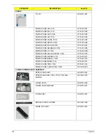
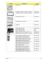
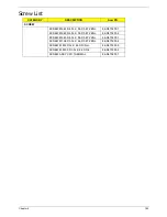
RAM DOOR ASSY
42.N3702.002
HDD DOOR ASSY
42.N3702.003
2ND HDD DOOR ASSY
42.N3702.004
MINI CARD BRK
33.PGY02.001
33.N6602.001
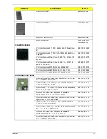
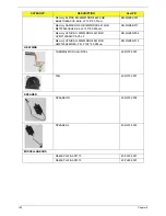
CPU/PROCESSOR
CPU Intel CeleronM T1600 1.66G 1M 667 Dual Core,
MV
KC.16001.CMT
CPU Intel CeleronM T1700 PGA 1.83G 1M 667 Dual
Core, MV
KC.17001.CMT
CPU Intel Pentium Dual-Core T3400 PGA 2.16G 1M
667 MV
KC.34001.DTP
CPU Intel Pentium Dual-Core T4200 PGA 2.0G 1M
800 35W R-0 no VT
KC.42001.DTP
CPU Intel Celeron 575 PGA 2.0G 1M 667 MV
KC.N0001.575
CPU Intel Celeron 585 PGA 2.16G 1M 667 MV
KC.N0001.585
CPU Intel Celeron 900 PGA 2.2G 1M 800 35W
KC.N0001.900
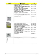
HDD/HARD DISK DRIVE
HDD SEAGATE 2.5" 5400rpm 160GB ST9160310AS
Crockett SATA LF F/W:0303
KH.16001.034
HDD TOSHIBA 2.5" 5400rpm 160GB MK1655GSX
Libra SATA LF F/W: FG011J
KH.16004.006
HDD HGST 2.5" 5400rpm 160GB HTS543216L9A300
Falcon-B SATA LF F/W:C40C
KH.16007.019
HDD WD 2.5" 5400rpm 160GB WD1600BEVT-
22ZCTO ML160 SATA LF F/W:11.01A11
KH.16008.022
HDD SEAGATE 2.5" 5400rpm 250GB ST9250315AS
Wyatt SATA LF F/W:0001SDM1
KH.25001.016
HDD TOSHIBA 2.5" 5400rpm 250GB MK2555GSX
Libra SATA LF F/W:FG001J
KH.25004.003
HDD HGST 2.5" 5400rpm 250GB HTS545025B9A300
Panther B SATA LF F/W:C60F
KH.25007.015
HDD WD 2.5" 5400rpm 250GB WD2500BEVT-
22ZCT0 ML160 SATA LF F/W:11.01A11
KH.25008.021
HDD SEAGATE 2.5" 5400rpm 320GB ST9320320AS
Crockett SATA LF F/W:0303
KH.32001.008
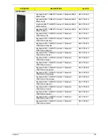
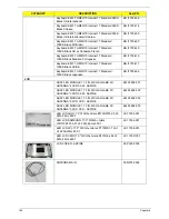
CATEGORY
DESCRIPTION
AcerPN
Содержание Aspire 7715Z Series
Страница 6: ...VI ...
Страница 10: ...X Table of Contents ...
Страница 13: ...Chapter 1 3 System Block Diagram ...
Страница 30: ...20 Chapter 1 ...
Страница 52: ...42 Chapter 2 ...
Страница 74: ...64 Chapter 3 4 Disconnect the following four cables from the Mainboard A B C D ...
Страница 87: ...Chapter 3 77 4 Using both hands lift the Thermal Module clear of the Mainboard ...
Страница 89: ...Chapter 3 79 4 Lift the CPU Fan clear of the Mainboard as shown ...
Страница 95: ...Chapter 3 85 5 Lift the LCD Panel clear of the module ...
Страница 103: ...Chapter 3 93 9 The Antennas and cables appear as shown when correctly installed ...
Страница 108: ...98 Chapter 3 2 Replace the four screws and screw caps provided ...
Страница 113: ...Chapter 3 103 5 Replace the FFC and press down as indicated to secure it to the Upper Cover ...
Страница 117: ...Chapter 3 107 2 Press down around the edges to secure it in place 3 Replace the nine screws in the Upper Cover as shown ...
Страница 118: ...108 Chapter 3 4 Replace the three screw caps as shown 5 Connect the following cables to the Mainboard A B C D ...
Страница 124: ...114 Chapter 3 17 Replace the two screws securing the LCD Module to the Lower Cover ...
Страница 132: ...122 Chapter 3 ...
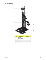
Страница 163: ...Chapter 6 153 Base Assembly No Description Acer P N 1 CPU Fan 2 Thermal Module 3 4 5 Mainboard 1 2 3 4 5 ...
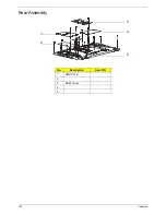
Страница 164: ...154 Chapter 6 Rear Assembly No Description Acer P N 1 HDD Cover 2 3 RAM Cover 4 5 1 2 3 4 5 ...
Страница 174: ...Appendix A 164 Model Definition and Configuration Appendix A ...
Страница 196: ...186 Appendix C ...
Страница 200: ...190 ...

