158
Chapter 6
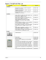
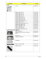
HDD TOSHIBA 2.5" 5400rpm 320GB MK3255GSX
Libra SATA LF F/W:FG011J
KH.32004.002
HDD HGST 2.5" 5400rpm 320GB HTS545032B9A300
Panther B SATA LF F/W: C60F
KH.32007.007
HDD WD 2.5" 5400rpm 320GB WD3200BEVT-
22ZCT0 ML160 SATA LF F/W:11.01A11
KH.32008.013
HDD SEAGATE 2.5" 5400rpm 500GB ST9500325AS
Wyatt SATA LF F/W:0001SDM1
KH.50001.011
HDD WD 2.5" 5400rpm 500GB WD5000BEVT-
22ZAT0 ML250 SATA LF F/W:01.01A01
KH.50008.013
HDD HGST 2.5" 5400rpm 500GB HTS545050B9A300
Panther B SATA LF F/W:C60F
KH.50007.009
HDD BRACKET ASSY
33.N3702.002
DVD DRIVE
DVD SUPER MULTI DRIVE MODULE
6M.N3702.001
DVD SUPER MULTI DRIVE MODULE - Win 7
6M.PL802.001
ODD PANASONIC Super-Multi DRIVE 12.7mm Tray
DL 8X UJ880A LF W/O bezel SATA
KU.00807.064
ODD HLDS Super-Multi DRIVE 12.7mm Tray DL 8X
GT20N LF W/O bezel SATA
KU.0080D.040
ODD SONY Super-Multi DRIVE 12.7mm Tray DL 8X
AD-7580S LF W/O bezel SATA
KU.0080E.017
ODD PLDS Super-Multi DRIVE 12.7mm Tray DL 8X
DS-8A3S LF W/O bezel SATA
KU.0080F.004
ODD BRACKET
33.N3702.003
ODD BEZEL-SUPER MULTI
42.N3702.005
CATEGORY
DESCRIPTION
AcerPN
Содержание Aspire 7715Z Series
Страница 6: ...VI ...
Страница 10: ...X Table of Contents ...
Страница 13: ...Chapter 1 3 System Block Diagram ...
Страница 30: ...20 Chapter 1 ...
Страница 52: ...42 Chapter 2 ...
Страница 74: ...64 Chapter 3 4 Disconnect the following four cables from the Mainboard A B C D ...
Страница 87: ...Chapter 3 77 4 Using both hands lift the Thermal Module clear of the Mainboard ...
Страница 89: ...Chapter 3 79 4 Lift the CPU Fan clear of the Mainboard as shown ...
Страница 95: ...Chapter 3 85 5 Lift the LCD Panel clear of the module ...
Страница 103: ...Chapter 3 93 9 The Antennas and cables appear as shown when correctly installed ...
Страница 108: ...98 Chapter 3 2 Replace the four screws and screw caps provided ...
Страница 113: ...Chapter 3 103 5 Replace the FFC and press down as indicated to secure it to the Upper Cover ...
Страница 117: ...Chapter 3 107 2 Press down around the edges to secure it in place 3 Replace the nine screws in the Upper Cover as shown ...
Страница 118: ...108 Chapter 3 4 Replace the three screw caps as shown 5 Connect the following cables to the Mainboard A B C D ...
Страница 124: ...114 Chapter 3 17 Replace the two screws securing the LCD Module to the Lower Cover ...
Страница 132: ...122 Chapter 3 ...
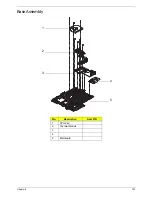
Страница 163: ...Chapter 6 153 Base Assembly No Description Acer P N 1 CPU Fan 2 Thermal Module 3 4 5 Mainboard 1 2 3 4 5 ...
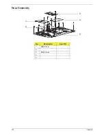
Страница 164: ...154 Chapter 6 Rear Assembly No Description Acer P N 1 HDD Cover 2 3 RAM Cover 4 5 1 2 3 4 5 ...
Страница 174: ...Appendix A 164 Model Definition and Configuration Appendix A ...
Страница 196: ...186 Appendix C ...
Страница 200: ...190 ...

