2
Chapter 1
•
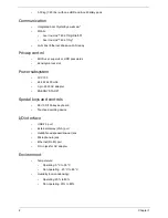
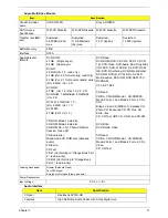
3.30 kg (7.29 lbs.) with one HDD and 6-cell battery pack
Communication
•
Integrated Acer Crystal Eye webcam*
•
WLAN:
•
Acer InviLink™ 802.11b/g/Draft-N*
•
Acer InviLink™ 802.11b/g*
•
LAN: Fast Ethernet; Wake-on-LAN ready
Privacy control
•
BIOS user, supervisor, HDD passwords
•
Kensington lock slot
Power subsystem
•
ACPI 3.0
•
48.8 W 4400 mAh
•
3-pin 65 W AC adapter
•
ENERGY STAR®*
Special keys and controls
•
99-/100-/103-key keyboard
•
Touchpad pointing device
I/O interface
•
USB 2.0 port
•
External display (VGA) port
•
Headphones/speaker/line-out jack
•
Microphone-in jack
•
Ethernet (RJ-45) port
•
DC-in jack for AC adapter
Environment
•
Temperature:
•
Operating: 5 °C to 35 °C
•
Non-operating: -20 °C to 65 °C
•
Humidity (non-condensing):
•
Operating: 20% to 80%
•
Non-operating: 20% to 80%
Содержание Aspire 7715Z Series
Страница 6: ...VI ...
Страница 10: ...X Table of Contents ...
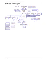
Страница 13: ...Chapter 1 3 System Block Diagram ...
Страница 30: ...20 Chapter 1 ...
Страница 52: ...42 Chapter 2 ...
Страница 74: ...64 Chapter 3 4 Disconnect the following four cables from the Mainboard A B C D ...
Страница 87: ...Chapter 3 77 4 Using both hands lift the Thermal Module clear of the Mainboard ...
Страница 89: ...Chapter 3 79 4 Lift the CPU Fan clear of the Mainboard as shown ...
Страница 95: ...Chapter 3 85 5 Lift the LCD Panel clear of the module ...
Страница 103: ...Chapter 3 93 9 The Antennas and cables appear as shown when correctly installed ...
Страница 108: ...98 Chapter 3 2 Replace the four screws and screw caps provided ...
Страница 113: ...Chapter 3 103 5 Replace the FFC and press down as indicated to secure it to the Upper Cover ...
Страница 117: ...Chapter 3 107 2 Press down around the edges to secure it in place 3 Replace the nine screws in the Upper Cover as shown ...
Страница 118: ...108 Chapter 3 4 Replace the three screw caps as shown 5 Connect the following cables to the Mainboard A B C D ...
Страница 124: ...114 Chapter 3 17 Replace the two screws securing the LCD Module to the Lower Cover ...
Страница 132: ...122 Chapter 3 ...
Страница 163: ...Chapter 6 153 Base Assembly No Description Acer P N 1 CPU Fan 2 Thermal Module 3 4 5 Mainboard 1 2 3 4 5 ...
Страница 164: ...154 Chapter 6 Rear Assembly No Description Acer P N 1 HDD Cover 2 3 RAM Cover 4 5 1 2 3 4 5 ...
Страница 174: ...Appendix A 164 Model Definition and Configuration Appendix A ...
Страница 196: ...186 Appendix C ...
Страница 200: ...190 ...


