14
Chapter 1
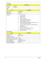
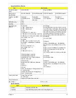
Southbridge
BIOS
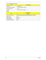
System Memory
Item
Specification
Chipset
ICH9-M
Package
BGA-676
Item
Specification
BIOS vendor
Insyde BIOS
BIOS Version
V0.06-T02
BIOS ROM type
Flash
Features
•
Flash ROM 1MB
•
Supports ISIPP
•
Supports Acer UI
•
Supports multi-boot
•
Suspend to RAM (S3)/Disk (S4)
•
Various hot-keys for system control
•
Supports SMBUS 2.0, PCI2.3
•
ACPI 2.0 compliance with Intel Speed Step support C1, C2,
C3, C4 and S3, S4 for mobile CPU
•
DMI utility for BIOS serial number configurable/asset tag
•
Supports PXE
•
Supports Y2K solution
•
Supports Win Flash Wake on LAN from S3
•
Wake on LAN form S4 in AC mode
•
System information
Item
Specification
Memory controller
ICH9-M
Memory size
4GB maximum
DIMM socket number
2
Supports memory size per socket
2GB
Supports maximum memory size
4GB (total)
Supports DIMM type
200-pin +1.8V DDRII
Supports DIMM Speed
667/800 MHz
Supports DIMM voltage
1.8V
Содержание Aspire 7715Z Series
Страница 6: ...VI ...
Страница 10: ...X Table of Contents ...
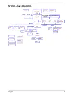
Страница 13: ...Chapter 1 3 System Block Diagram ...
Страница 30: ...20 Chapter 1 ...
Страница 52: ...42 Chapter 2 ...
Страница 74: ...64 Chapter 3 4 Disconnect the following four cables from the Mainboard A B C D ...
Страница 87: ...Chapter 3 77 4 Using both hands lift the Thermal Module clear of the Mainboard ...
Страница 89: ...Chapter 3 79 4 Lift the CPU Fan clear of the Mainboard as shown ...
Страница 95: ...Chapter 3 85 5 Lift the LCD Panel clear of the module ...
Страница 103: ...Chapter 3 93 9 The Antennas and cables appear as shown when correctly installed ...
Страница 108: ...98 Chapter 3 2 Replace the four screws and screw caps provided ...
Страница 113: ...Chapter 3 103 5 Replace the FFC and press down as indicated to secure it to the Upper Cover ...
Страница 117: ...Chapter 3 107 2 Press down around the edges to secure it in place 3 Replace the nine screws in the Upper Cover as shown ...
Страница 118: ...108 Chapter 3 4 Replace the three screw caps as shown 5 Connect the following cables to the Mainboard A B C D ...
Страница 124: ...114 Chapter 3 17 Replace the two screws securing the LCD Module to the Lower Cover ...
Страница 132: ...122 Chapter 3 ...
Страница 163: ...Chapter 6 153 Base Assembly No Description Acer P N 1 CPU Fan 2 Thermal Module 3 4 5 Mainboard 1 2 3 4 5 ...
Страница 164: ...154 Chapter 6 Rear Assembly No Description Acer P N 1 HDD Cover 2 3 RAM Cover 4 5 1 2 3 4 5 ...
Страница 174: ...Appendix A 164 Model Definition and Configuration Appendix A ...
Страница 196: ...186 Appendix C ...
Страница 200: ...190 ...


