160
Chapter 6
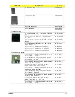
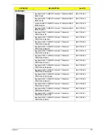
Keyboard EM-7T HM50/70 Internal 17 Standard 99KS
Black US International
KB.I1700.438
Keyboard EM-7T HM50/70 Internal 17 Standard 99KS
Black Chinese
KB.I1700.418
Keyboard EM-7T HM50/70 Internal 17 Standard 99KS
Black US International w/ Hebrew
KB.I1700.439
Keyboard EM-7T HM50/70 Internal 17 Standard
100KS Black FR/Arabic
KB.I1700.420
Keyboard EM-7T HM50/70 Internal 17 Standard
100KS Black US w/ Canadian French
KB.I1700.440
Keyboard EM-7T HM50/70 Internal 17 Standard
100KS Black Brazilian Portuguese
KB.I1700.416
Keyboard EM-7T HM50/70 Internal 17 Standard
100KS Black CZ/SK
KB.I1700.417
Keyboard EM-7T HM50/70 Internal 17 Standard
103KS Black Japanese
KB.I1700.426
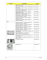
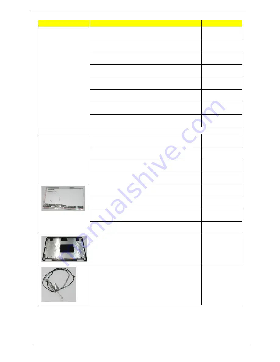
LCD
ASSY LED MODULE 17.3 IN. WXGA GLARE W/
ANTENNA*2 CCD 0.3M - ASPIRE
6M.PL602.001
ASSY LED MODULE 17.3 IN. WXGA GLARE W/
ANTENNA*3 CCD 0.3M - ASPIRE
6M.PL602.002
ASSY LED MODULE 17.3 IN. WXGA GLARE W/
ANTENNA*2, W/O CCD - ASPIRE
6M.PL802.002
ASSY LED MODULE 17.3 IN. WXGA GLARE W/
ANTENNA*3, W/O CCD - ASPIRE
6M.PL802.003
LED LCD AUO 17.3" WXGA+ Glare B173RW01-V0 LF
220nit 8ms 600:1
LK.17305.001
LED LCD SAMSUNG 17.3" WXGA+ Glare
LTN173KT01-A01 LF 220nit 8ms 600:1
LK.17306.001
LED LCD LPL 17.3" WXGA+ Glare LP173WD1-TLA1
LF 220nit 8ms 600:1
LK.17308.001
LED LCD CMO 17.3" WXGA+ Glare N173O6-L02 LF
220nit 8ms 600:1
LK.1730D.001
LCD COVER - ASPIRE
60.PL602.003
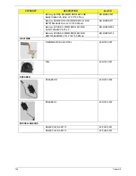
ANTENNA MAIN
50.N3702.002
CATEGORY
DESCRIPTION
AcerPN
Содержание Aspire 7715Z Series
Страница 6: ...VI ...
Страница 10: ...X Table of Contents ...
Страница 13: ...Chapter 1 3 System Block Diagram ...
Страница 30: ...20 Chapter 1 ...
Страница 52: ...42 Chapter 2 ...
Страница 74: ...64 Chapter 3 4 Disconnect the following four cables from the Mainboard A B C D ...
Страница 87: ...Chapter 3 77 4 Using both hands lift the Thermal Module clear of the Mainboard ...
Страница 89: ...Chapter 3 79 4 Lift the CPU Fan clear of the Mainboard as shown ...
Страница 95: ...Chapter 3 85 5 Lift the LCD Panel clear of the module ...
Страница 103: ...Chapter 3 93 9 The Antennas and cables appear as shown when correctly installed ...
Страница 108: ...98 Chapter 3 2 Replace the four screws and screw caps provided ...
Страница 113: ...Chapter 3 103 5 Replace the FFC and press down as indicated to secure it to the Upper Cover ...
Страница 117: ...Chapter 3 107 2 Press down around the edges to secure it in place 3 Replace the nine screws in the Upper Cover as shown ...
Страница 118: ...108 Chapter 3 4 Replace the three screw caps as shown 5 Connect the following cables to the Mainboard A B C D ...
Страница 124: ...114 Chapter 3 17 Replace the two screws securing the LCD Module to the Lower Cover ...
Страница 132: ...122 Chapter 3 ...
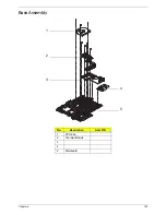
Страница 163: ...Chapter 6 153 Base Assembly No Description Acer P N 1 CPU Fan 2 Thermal Module 3 4 5 Mainboard 1 2 3 4 5 ...
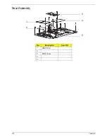
Страница 164: ...154 Chapter 6 Rear Assembly No Description Acer P N 1 HDD Cover 2 3 RAM Cover 4 5 1 2 3 4 5 ...
Страница 174: ...Appendix A 164 Model Definition and Configuration Appendix A ...
Страница 196: ...186 Appendix C ...
Страница 200: ...190 ...

