4-16
Service Guide
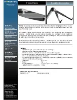
4.6.5 Detaching the Top Cover
Follow these steps to detach the top cover from the bottom cover:
1.
Unplug the touchpad cable (CN6) from the keyboard/touchpad board, and the audio board
cable (CN14), speaker cables (CN13 and CN15) and optionally, the fan connector found just
above the speaker cables (CN12) from the mainboard.
Figure 4-18
Removing Cables
2.
Detach the top cover from the bottom cover.
Figure 4-19
Detaching the Top Cover
Содержание 390 Series
Страница 14: ...1 2 Service Guide 1 2 System Board Layout 1 2 1 Mainboard Figure 1 1 PCB No 96183 1A Mainboard Layout Top ...
Страница 15: ...System Introduction 1 3 Figure 1 2 PCB No 96183 1A Mainboard Layout Bottom ...
Страница 96: ...2 50 Service Guide 2 3 3 Pin Configuration Figure 2 4 FDC37C67 TQFP Pin Diagram ...
Страница 97: ...Major Chips Description 2 51 Figure 2 5 FDC37C67 QFP Pin Diagram ...
Страница 102: ...2 56 Service Guide 2 3 6 Block Diagram Figure 2 6 FDC37C67 Block Diagram ...
Страница 111: ...Major Chips Description 2 65 2 4 4 3 Bottom View BGA Ball Assignments Figure 2 8 65555 BGA Ball Assignments Bottom View ...
Страница 126: ...2 80 Service Guide 2 5 4 1 Functional Block Diagram Figure 2 10 M38813 Block Diagram ...
Страница 128: ...2 82 Service Guide 2 6 2 Pin Diagram Figure 2 11 YMF715 Block Diagram ...
Страница 168: ......
Страница 169: ......
Страница 170: ......
Страница 171: ......
Страница 172: ......
Страница 173: ......