3.3.7 Fitting equipment on the robot (robot dimensions)
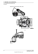
Attachment holes and dimensions
Definitions of dimensions are shown in the following figures. The robot is supplied
with holes for fitting extra equipment.
Holes for fitting extra equipment
55
2xM4
8
72,5
X
490
15
30
Y
30
15
30
400
30
353,5
467
8xM6-
12
same at two side
8xM6-
12
same at two side
B
264,5
30
230
202
2xM6
12
xx2300000170
1.05_0.45
1.05_0.3
0.85_0.45
0.85_0.3
560 mm
560 mm
360 mm
360 mm
X
530 mm
530 mm
330 mm
330 mm
Y
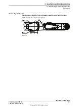
Gravity for different arm loads
Arm loads can be mounted on the axis 2. The center of gravity of the extra load
shall be within the marked load areas. The robot is supplied with holes for mounting
of extra equipment. (See figures in Holes for mounting of extra equipment.)
Note
Maximum load on the frame must not be exceeded.
Continues on next page
64
Product manual - IRB 930
3HAC086009-001 Revision: A
© Copyright 2023 ABB. All rights reserved.
3 Installation and commissioning
3.3.7 Fitting equipment on the robot (robot dimensions)
Содержание IRB 930
Страница 1: ...ROBOTICS Product manual IRB 930 ...
Страница 2: ...Trace back information Workspace 23B version a11 Checked in 2023 06 20 Skribenta version 5 5 019 ...
Страница 8: ...This page is intentionally left blank ...
Страница 14: ...This page is intentionally left blank ...
Страница 78: ...This page is intentionally left blank ...
Страница 600: ...This page is intentionally left blank ...
Страница 604: ......
Страница 605: ......

