


Calibration
Repairs
56
Product Manual IRB 6400R
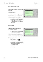
14. The “Master Robot Project Screen” appears with a picture of the manipulator.
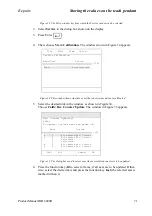
15. To start the measurement procedure, click the “Measure” button.
16. A dialog box appears telling you to make sure that the measurement cable is at the
reference position on the DynaCal Calibration unit.
Note! Make sure that the cable attachment is placed in the reference position
to establish the zero point for the measurement process. Click OK.
17. Now the “Measurement Screen” window appears.
At this stage you should read a value of approx. 101.8. Pull the cable out and
in a couple of times by hand and then place it in it’s reference position again
and check that you have approx. the same value as from the beginning.
18. Now position the hook on the measurement cable onto the calibration adaptor
(mounted on the calibration tool). Make sure that the hook is properly engaged.
The calibration positions of the robot are done, using the teach pendant. Move the robot
to each position and store the position. Before moving the robot again you also teach
the measurement point by clicking the “Measure” button in the “Measuring Screen”.
The number of positions should be between 20 -30. The calibration positions should
cause as much change as possible in the tool orientation, and the robot should move to
its extremes (minimum reach and maximum reach). For convenience you may select
positions in a 1x1x1 m cube. Note that the angle at the joint coupling of the calibration
adapter at the end of the cable should not exceed 90 degrees.
19. Move the robot to the first position and store the position in the robot program.
Make sure that you have the right TCP activated.
20. At this position, also measure the point by clicking the “Measure” button or using
the “M” key of the keyboard. Make sure that the cable itself is not in contact with
any part of the robot or the fixtures present in the cell.
21. Continue in the same way with all of the other positions.
22. After the last position, place the cable in its reference position.
23. The default name for the measurement position file is DynaCal/1.msr (the name
can be changed by typing a new file name).
24. Then click OK in the “Measurement Screen” window.
25. A “Measurement Complete” message appears.
26. The measurement file will show up in the “Measurement files” box of the project
window.
27. Copy the robot program with the 20-30 positions to a diskette as a module.
File: “Save Module as”.
28. Insert the diskette into the PC.
Содержание IRB 6400R
Страница 4: ...Description 20 Product Specification IRB 1400 M97A BaseWare OS 3 0 ...
Страница 6: ...Introduction 2 Product Manual ...
Страница 10: ...Introduction 6 Product Manual ...
Страница 12: ...Product Specification IRB 6400R 2 Product Specification IRB 6400R M99 BaseWare OS 3 2 ...
Страница 78: ...Accessories 68 Product Specification IRB 6400R M99 BaseWare OS 3 2 ...
Страница 80: ...Product Specification RobotWare 2 Product Specification RobotWare for BaseWare OS 3 2 ...
Страница 82: ...Introduction 4 Product Specification RobotWare for BaseWare OS 3 2 ...
Страница 104: ...Interbus S 3 2 26 Product Specification RobotWare for BaseWare OS 3 2 ...
Страница 110: ...I O Plus 3 2 32 Product Specification RobotWare for BaseWare OS 3 2 ...
Страница 128: ...PalletWare 50 Product Specification RobotWare for BaseWare OS 3 2 ...
Страница 132: ...Safety 2 Product Manual ...
Страница 148: ...System Description CONTENTS Page 2 Product Manual ...
Страница 158: ...Structure System Description 12 Product Manual ...
Страница 160: ...Computer System System Description 14 Product Manual ...
Страница 164: ...I O System System Description 18 Product Manual ...
Страница 168: ...Safety System System Description 22 Product Manual ...
Страница 170: ...External Axes System Description 24 Product Manual ...
Страница 174: ...Installation and Commissioning CONTENTS Page 4 Product Manual IRB 6400R ...
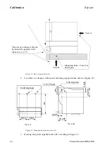
Страница 193: ...Installation and Commissioning On Site Installation Product Manual IRB 6400R 23 Figure 17 Cutting the cam Remove 90 30 ...
Страница 196: ...On Site Installation Installation and Commissioning 26 Product Manual IRB 6400R ...
Страница 270: ...Installing the Control Program Installation and Commissioning 100 Product Manual IRB 6400R ...
Страница 292: ...Maintenance CONTENTS Page 2 Product Manual IRB 6400R ...
Страница 299: ...Maintenance Product Manual IRB 6400R 9 Figure 4 Lubricating gearbox axis 1 4 3 1 2 ...
Страница 312: ...Troubleshooting Tools CONTENTS Page 2 Product Manual ...
Страница 350: ...Troubleshooting Tools 40 Product Manual ...
Страница 352: ...Fault tracing guide 2 Product Manual ...
Страница 362: ...Fault tracing guide 12 Product Manual ...
Страница 375: ...Motor units Repairs 12 Product Manual IRB 6400R ...
Страница 401: ...Arm System Repairs 38 Product Manual IRB 6400R ...
Страница 409: ...Cabling Repairs 46 Product Manual IRB 6400R ...
Страница 441: ...Special Tools List Repairs 80 Product Manual IRB 6400R ...
Страница 479: ...Part List and Spare Parts Product Manual IRB 6400R 38 ...
Страница 480: ...Part List and Spare Parts Product Manual IRB 6400R 39 ...
Страница 481: ...Part List and Spare Parts Product Manual IRB 6400R 40 ...


