


Safety
Product Manual
7
7.2 Emergency stops
An emergency stop should be activated if there is a danger to people or equipment.
Built-in emergency stop buttons are located on the operator’s panel of the robot con-
troller and on the teach pendant.
External emergency stop devices (buttons, etc.) can be connected to the safety chain
by the user (see Product Manual/Installation). They must be connected in accordance
with the applicable standards for emergency stop circuits.
Before commissioning the robot, all emergency stop buttons or other safety equipment
must be checked by the user to ensure their proper operation.
Before switching to MOTORS ON mode again, establish the reason for the stop
and rectify the fault.
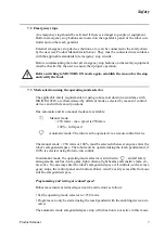
7.3 Mode selection using the operating mode selector
The applicable safety requirements for using robots, laid down in accordance with
ISO/DIS 10218, are characterised by different modes, selected by means of control
devices and with clear-cut positions.
One automatic and two manual modes are available:
The manual mode, < 250 mm/s or 100%, must be selected whenever anyone enters the
robot’s safeguarded space. The robot must be operated using the teach pendant and, if
100% is selected, using Hold-to-run control.
In automatic mode, the operating mode selector is switched to
, and all safety
arrangements, such as doors, gates, light curtains, light beams and sensitive mats, etc.,
are active. No-one may enter the robot’s safeguarded space. All controls, such as emer-
gency stops, the control panel and control cabinet, must be easily accessible from out-
side the safeguarded space.
Programming and testing at reduced speed
Robot movements at reduced speed can be carried out as follows:
• Set the operating mode selector to <250 mm/s
• Programs can only be started using the teach pendant with the enabling device acti-
vated.
The automatic mode safeguarded space stop (AS) function is not active in this mode.
Manual mode:
< 250 mm/s - max. speed is 250mm/s
100% - full speed
Automatic mode: The robot can be operated via a remote control device
Содержание IRB 6400R
Страница 4: ...Description 20 Product Specification IRB 1400 M97A BaseWare OS 3 0 ...
Страница 6: ...Introduction 2 Product Manual ...
Страница 10: ...Introduction 6 Product Manual ...
Страница 12: ...Product Specification IRB 6400R 2 Product Specification IRB 6400R M99 BaseWare OS 3 2 ...
Страница 78: ...Accessories 68 Product Specification IRB 6400R M99 BaseWare OS 3 2 ...
Страница 80: ...Product Specification RobotWare 2 Product Specification RobotWare for BaseWare OS 3 2 ...
Страница 82: ...Introduction 4 Product Specification RobotWare for BaseWare OS 3 2 ...
Страница 104: ...Interbus S 3 2 26 Product Specification RobotWare for BaseWare OS 3 2 ...
Страница 110: ...I O Plus 3 2 32 Product Specification RobotWare for BaseWare OS 3 2 ...
Страница 128: ...PalletWare 50 Product Specification RobotWare for BaseWare OS 3 2 ...
Страница 132: ...Safety 2 Product Manual ...
Страница 148: ...System Description CONTENTS Page 2 Product Manual ...
Страница 158: ...Structure System Description 12 Product Manual ...
Страница 160: ...Computer System System Description 14 Product Manual ...
Страница 164: ...I O System System Description 18 Product Manual ...
Страница 168: ...Safety System System Description 22 Product Manual ...
Страница 170: ...External Axes System Description 24 Product Manual ...
Страница 174: ...Installation and Commissioning CONTENTS Page 4 Product Manual IRB 6400R ...
Страница 193: ...Installation and Commissioning On Site Installation Product Manual IRB 6400R 23 Figure 17 Cutting the cam Remove 90 30 ...
Страница 196: ...On Site Installation Installation and Commissioning 26 Product Manual IRB 6400R ...
Страница 270: ...Installing the Control Program Installation and Commissioning 100 Product Manual IRB 6400R ...
Страница 292: ...Maintenance CONTENTS Page 2 Product Manual IRB 6400R ...
Страница 299: ...Maintenance Product Manual IRB 6400R 9 Figure 4 Lubricating gearbox axis 1 4 3 1 2 ...
Страница 312: ...Troubleshooting Tools CONTENTS Page 2 Product Manual ...
Страница 350: ...Troubleshooting Tools 40 Product Manual ...
Страница 352: ...Fault tracing guide 2 Product Manual ...
Страница 362: ...Fault tracing guide 12 Product Manual ...
Страница 375: ...Motor units Repairs 12 Product Manual IRB 6400R ...
Страница 401: ...Arm System Repairs 38 Product Manual IRB 6400R ...
Страница 409: ...Cabling Repairs 46 Product Manual IRB 6400R ...
Страница 441: ...Special Tools List Repairs 80 Product Manual IRB 6400R ...
Страница 479: ...Part List and Spare Parts Product Manual IRB 6400R 38 ...
Страница 480: ...Part List and Spare Parts Product Manual IRB 6400R 39 ...
Страница 481: ...Part List and Spare Parts Product Manual IRB 6400R 40 ...


