


Installation and Commissioning
Connecting Signals
Product Manual IRB 6400R
39
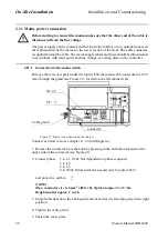
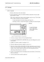
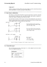
3.5 Connections
Detailed information about connection locations and functions will be found in chapter
11, Circuit Diagram.
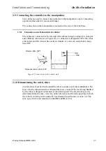
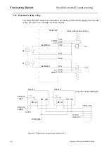
3.5.1 To screw terminal
Panel unit and I/O units are provided with keyed screw terminals for cables with an
area between 0.25 and 1.5 mm
2
. A maximum of two cables may be used in any one
connection. The cable screen must be connected to the cabinet wall using EMC. It
should be noted that the screen must continue right up to the screw terminal.
The installation should comply with the IP54 (NEMA 12) protective standard.
Bend unused conductors backwards and attach them to the cable using a clasp, for
example. In order to prevent interference, ensure that such conductors are not con-
nected at the other end of the cable (antenna effect). In environments with much inter-
ference, disconnected conductors should be grounded (0 V) at both ends.
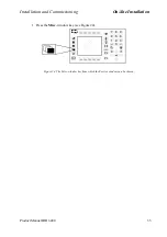
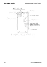
3.5.2 To connectors (option)
Industrial connectors with 4x16 pins for contact crimping (complies with DIN 43652)
can be found on the left-hand side or front of the cabinet (depending on the customer
order) See Figure 30 and Figure 21.
In each industrial connector there is space for four rows of 16 conductors with a max-
imum conductor area of 1.5 mm
2
. The pull-relief clamp must be used when connecting
the shield to the case.
The manipulator arm is equipped with round Burndy/Framatome connectors (customer
connector not included).
Bend unused conductors backwards and attach them to the cable using a clasp, for
example. In order to prevent interference, ensure that such conductors are not con-
nected at the other end of the cable (antenna effect). In environments with much inter-
ference, disconnected conductors should be grounded (0 V) at both ends.
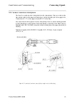
When contact crimping industrial connectors, the following applies:
Using special tongs, press a pin or socket on to each non-insulated conductor.
The pin can then be snapped into the actual contact.
Push the pin into the connector until it locks.
Also, see instructions from contact supplier.
A special extractor tool must be used to remove pins from industrial connectors.
When two conductors must be connected to the same pin, both of them are pressed into
the same pin. A maximum of two conductors may be pressed into any one pin.
Содержание IRB 6400R
Страница 4: ...Description 20 Product Specification IRB 1400 M97A BaseWare OS 3 0 ...
Страница 6: ...Introduction 2 Product Manual ...
Страница 10: ...Introduction 6 Product Manual ...
Страница 12: ...Product Specification IRB 6400R 2 Product Specification IRB 6400R M99 BaseWare OS 3 2 ...
Страница 78: ...Accessories 68 Product Specification IRB 6400R M99 BaseWare OS 3 2 ...
Страница 80: ...Product Specification RobotWare 2 Product Specification RobotWare for BaseWare OS 3 2 ...
Страница 82: ...Introduction 4 Product Specification RobotWare for BaseWare OS 3 2 ...
Страница 104: ...Interbus S 3 2 26 Product Specification RobotWare for BaseWare OS 3 2 ...
Страница 110: ...I O Plus 3 2 32 Product Specification RobotWare for BaseWare OS 3 2 ...
Страница 128: ...PalletWare 50 Product Specification RobotWare for BaseWare OS 3 2 ...
Страница 132: ...Safety 2 Product Manual ...
Страница 148: ...System Description CONTENTS Page 2 Product Manual ...
Страница 158: ...Structure System Description 12 Product Manual ...
Страница 160: ...Computer System System Description 14 Product Manual ...
Страница 164: ...I O System System Description 18 Product Manual ...
Страница 168: ...Safety System System Description 22 Product Manual ...
Страница 170: ...External Axes System Description 24 Product Manual ...
Страница 174: ...Installation and Commissioning CONTENTS Page 4 Product Manual IRB 6400R ...
Страница 193: ...Installation and Commissioning On Site Installation Product Manual IRB 6400R 23 Figure 17 Cutting the cam Remove 90 30 ...
Страница 196: ...On Site Installation Installation and Commissioning 26 Product Manual IRB 6400R ...
Страница 270: ...Installing the Control Program Installation and Commissioning 100 Product Manual IRB 6400R ...
Страница 292: ...Maintenance CONTENTS Page 2 Product Manual IRB 6400R ...
Страница 299: ...Maintenance Product Manual IRB 6400R 9 Figure 4 Lubricating gearbox axis 1 4 3 1 2 ...
Страница 312: ...Troubleshooting Tools CONTENTS Page 2 Product Manual ...
Страница 350: ...Troubleshooting Tools 40 Product Manual ...
Страница 352: ...Fault tracing guide 2 Product Manual ...
Страница 362: ...Fault tracing guide 12 Product Manual ...
Страница 375: ...Motor units Repairs 12 Product Manual IRB 6400R ...
Страница 401: ...Arm System Repairs 38 Product Manual IRB 6400R ...
Страница 409: ...Cabling Repairs 46 Product Manual IRB 6400R ...
Страница 441: ...Special Tools List Repairs 80 Product Manual IRB 6400R ...
Страница 479: ...Part List and Spare Parts Product Manual IRB 6400R 38 ...
Страница 480: ...Part List and Spare Parts Product Manual IRB 6400R 39 ...
Страница 481: ...Part List and Spare Parts Product Manual IRB 6400R 40 ...


