


Connecting Signals
Installation and Commissioning
84
Product Manual IRB 6400R
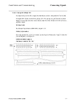
When the robot is last in a RIO loop, the loop must be terminated with a termination
resistor according to Allen-Bradley’s specification.
This product incorporates a communications link which is licensed under patents and proprietary technology of
Allen-Bradley Company, Inc. Allen-Bradley Company, Inc. does not warrant or support this product. All warranty
and support services for this product are the responsibility of and provided by ABB Flexible Automation.
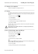
RIO communication concept
Figure 53 RIO communication concept - Principle diagram
The Allen Bradley system can communicate with up to 64 external systems. Each of
these systems is called a Rack and is given a Rack Address 0-63. Basically, each robot
connected to the Allen Bradley system will occupy 1 rack.
Each rack is divided into 4 sections called Quarters. Each quarter provides 32 inputs
and 32 outputs and a rack will subsequently provide 128 inputs and 128 outputs.
A rack may also be shared by 2, 3 or 4 robots. Each of these robots will then have the
same rack address, but different starting quarters must be specified.
The illustration above shows an example where Robot 1 uses a full rack while robot 2
and robot 3 share 1 rack.
The rack address, starting quarter and other required parameters such as baud rate, LED
Status etc. are entered in the configuration parameters.
The robot may communicate with the Allen Bradley system only, or be used in combi-
nation with I/O system in the robot. For example, the inputs to the robot may come from
the Allen Bradley system while the outputs from the robot control external equipment
via general I/O addresses and the Allen Bradley system only reads the outputs as status
signals.
Allen Bradley
control system
Robot 1 - 128 in / 128 out
Robot 2 - 64 in / 64 out
128 in / 128 out
64 in / 64 out
Quarter 2
Quarter 3
Quarter 4
Quarter 1
Rack ID 12 (example)
Rack size 4
Starting quarter 1
Quarter 2
Quarter 1
Rack ID 13 (example)
Rack size 2
Starting quarter 1
Robot 3 - 64 in / 64 out
64 in / 64 out
Quarter 4
Quarter 3
Rack ID 13 (example)
Rack size 2
Starting quarter 3
Quarter 2
Quarter 3
Quarter 4
Quarter 1
Other systems
Содержание IRB 6400R
Страница 4: ...Description 20 Product Specification IRB 1400 M97A BaseWare OS 3 0 ...
Страница 6: ...Introduction 2 Product Manual ...
Страница 10: ...Introduction 6 Product Manual ...
Страница 12: ...Product Specification IRB 6400R 2 Product Specification IRB 6400R M99 BaseWare OS 3 2 ...
Страница 78: ...Accessories 68 Product Specification IRB 6400R M99 BaseWare OS 3 2 ...
Страница 80: ...Product Specification RobotWare 2 Product Specification RobotWare for BaseWare OS 3 2 ...
Страница 82: ...Introduction 4 Product Specification RobotWare for BaseWare OS 3 2 ...
Страница 104: ...Interbus S 3 2 26 Product Specification RobotWare for BaseWare OS 3 2 ...
Страница 110: ...I O Plus 3 2 32 Product Specification RobotWare for BaseWare OS 3 2 ...
Страница 128: ...PalletWare 50 Product Specification RobotWare for BaseWare OS 3 2 ...
Страница 132: ...Safety 2 Product Manual ...
Страница 148: ...System Description CONTENTS Page 2 Product Manual ...
Страница 158: ...Structure System Description 12 Product Manual ...
Страница 160: ...Computer System System Description 14 Product Manual ...
Страница 164: ...I O System System Description 18 Product Manual ...
Страница 168: ...Safety System System Description 22 Product Manual ...
Страница 170: ...External Axes System Description 24 Product Manual ...
Страница 174: ...Installation and Commissioning CONTENTS Page 4 Product Manual IRB 6400R ...
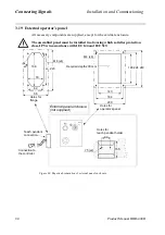
Страница 193: ...Installation and Commissioning On Site Installation Product Manual IRB 6400R 23 Figure 17 Cutting the cam Remove 90 30 ...
Страница 196: ...On Site Installation Installation and Commissioning 26 Product Manual IRB 6400R ...
Страница 270: ...Installing the Control Program Installation and Commissioning 100 Product Manual IRB 6400R ...
Страница 292: ...Maintenance CONTENTS Page 2 Product Manual IRB 6400R ...
Страница 299: ...Maintenance Product Manual IRB 6400R 9 Figure 4 Lubricating gearbox axis 1 4 3 1 2 ...
Страница 312: ...Troubleshooting Tools CONTENTS Page 2 Product Manual ...
Страница 350: ...Troubleshooting Tools 40 Product Manual ...
Страница 352: ...Fault tracing guide 2 Product Manual ...
Страница 362: ...Fault tracing guide 12 Product Manual ...
Страница 375: ...Motor units Repairs 12 Product Manual IRB 6400R ...
Страница 401: ...Arm System Repairs 38 Product Manual IRB 6400R ...
Страница 409: ...Cabling Repairs 46 Product Manual IRB 6400R ...
Страница 441: ...Special Tools List Repairs 80 Product Manual IRB 6400R ...
Страница 479: ...Part List and Spare Parts Product Manual IRB 6400R 38 ...
Страница 480: ...Part List and Spare Parts Product Manual IRB 6400R 39 ...
Страница 481: ...Part List and Spare Parts Product Manual IRB 6400R 40 ...


