


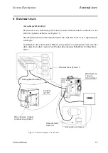


Safety System
System Description
20
Product Manual
If any of the dual switches in the safety circuit are opened, the circuit breaks, the motor
contactors drop out, and the robot is stopped by the brakes. If the safety circuit breaks,
an interrupt call is sent directly from the panel unit to the robot computer to ensure that
the cause of the interrupt is indicated.
When the robot is stopped by a limit switch, it can be moved from this position by jogging
it with the joystick while pressing the MOTORS ON button. The MOTORS ON button is
monitored and may be depressed for a maximum of 30 seconds.
LEDs for ES, AS and GS are connected to the two safety circuits to enable quick location
of the position where the safety chain is broken. The LEDs are located on the upper part of
the panel unit. Status indication is also available on the teach pendant display.
5.2 MOTORS ON and MOTORS OFF modes
The principle task of the safety circuit is to ensure that the robot goes into MOTORS
OFF mode as soon as any part of the chain is broken. The robot computer itself controls
the last switches (ENABLE and MOTORS ON).
In AUTO mode, you can switch the robot back on by pressing the MOTORS ON button on
the operator’s panel. If the circuit is OK, the robot computer then closes the MOTORS ON
relay to complete the circuit. When switching to MANUAL, the mode changes to
MOTORS OFF, at which stage the robot computer also opens the MOTORS ON relay. If
the robot mode does not change to MOTORS OFF, the ENABLE chain will break and the
ENABLE relay is opened. The safety circuit can thus be broken in two places by the robot
computer.
In any of the MANUAL modes, you can start operating again by pressing the enabling
device on the teach pendant. If the circuit is OK, the robot computer then closes the
MOTORS ON relay to complete the circuit. The function of the safety circuit can be
described as a combination of mechanical switches and robot computer controlled
relays which are all continuously monitored by the robot computer.
5.3 Safety stop signals
According to the safety standard ISO/DIS 11161 “Industrial automation systems -
safety of integrated manufacturing systems - Basic requirements”, there are two cate-
gories of safety stops, category 0 and category 1, see below:
The category 0 stop is to be used for safety analysis purposes, when the power supply to the
motors must be switched off immediately, such as when a light curtain, used to protect
against entry into the work cell, is passed. This uncontrolled motion stop may require spe-
cial restart routines if the programmed path changes as a result of the stop.
Category 1 is preferred for safety analysis purposes, if it is acceptable, such as when
gates are used to protect against entry into the work cell. This controlled motion stop
takes place within the programmed path, which makes restarting easier.
All the robot’s safety stops are category 0 stops as default.
Safety stops of category 1 can be obtained by activating the soft stop (delayed stop)
together with AS or GS. Activation is made by setting a parameter, see User’s Guide,
section System Parameters, Topic: Controller.
Содержание IRB 6400R
Страница 4: ...Description 20 Product Specification IRB 1400 M97A BaseWare OS 3 0 ...
Страница 6: ...Introduction 2 Product Manual ...
Страница 10: ...Introduction 6 Product Manual ...
Страница 12: ...Product Specification IRB 6400R 2 Product Specification IRB 6400R M99 BaseWare OS 3 2 ...
Страница 78: ...Accessories 68 Product Specification IRB 6400R M99 BaseWare OS 3 2 ...
Страница 80: ...Product Specification RobotWare 2 Product Specification RobotWare for BaseWare OS 3 2 ...
Страница 82: ...Introduction 4 Product Specification RobotWare for BaseWare OS 3 2 ...
Страница 104: ...Interbus S 3 2 26 Product Specification RobotWare for BaseWare OS 3 2 ...
Страница 110: ...I O Plus 3 2 32 Product Specification RobotWare for BaseWare OS 3 2 ...
Страница 128: ...PalletWare 50 Product Specification RobotWare for BaseWare OS 3 2 ...
Страница 132: ...Safety 2 Product Manual ...
Страница 148: ...System Description CONTENTS Page 2 Product Manual ...
Страница 158: ...Structure System Description 12 Product Manual ...
Страница 160: ...Computer System System Description 14 Product Manual ...
Страница 164: ...I O System System Description 18 Product Manual ...
Страница 168: ...Safety System System Description 22 Product Manual ...
Страница 170: ...External Axes System Description 24 Product Manual ...
Страница 174: ...Installation and Commissioning CONTENTS Page 4 Product Manual IRB 6400R ...
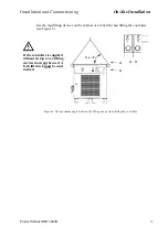
Страница 193: ...Installation and Commissioning On Site Installation Product Manual IRB 6400R 23 Figure 17 Cutting the cam Remove 90 30 ...
Страница 196: ...On Site Installation Installation and Commissioning 26 Product Manual IRB 6400R ...
Страница 270: ...Installing the Control Program Installation and Commissioning 100 Product Manual IRB 6400R ...
Страница 292: ...Maintenance CONTENTS Page 2 Product Manual IRB 6400R ...
Страница 299: ...Maintenance Product Manual IRB 6400R 9 Figure 4 Lubricating gearbox axis 1 4 3 1 2 ...
Страница 312: ...Troubleshooting Tools CONTENTS Page 2 Product Manual ...
Страница 350: ...Troubleshooting Tools 40 Product Manual ...
Страница 352: ...Fault tracing guide 2 Product Manual ...
Страница 362: ...Fault tracing guide 12 Product Manual ...
Страница 375: ...Motor units Repairs 12 Product Manual IRB 6400R ...
Страница 401: ...Arm System Repairs 38 Product Manual IRB 6400R ...
Страница 409: ...Cabling Repairs 46 Product Manual IRB 6400R ...
Страница 441: ...Special Tools List Repairs 80 Product Manual IRB 6400R ...
Страница 479: ...Part List and Spare Parts Product Manual IRB 6400R 38 ...
Страница 480: ...Part List and Spare Parts Product Manual IRB 6400R 39 ...
Страница 481: ...Part List and Spare Parts Product Manual IRB 6400R 40 ...


