


Repairs
Motors and Gears Axes 4-6
Product Manual IRB 6400R
21
4.7 Motor/gear axis 6.
Refer to foldout no 2:11§
It is not necessary to remove the wrist from the upper arm.
Dismounting:
1.
Dismount cabling for axis 6 as described in Chapter 7.3, Cabling, axis 6.
2.
Drain the grease. Open both magnetic plugs.
3.
Loosen screw <2:11/31> and remove the cover <2:11/38> Note! It is not neces-
sary to drain the wrist, before removing the cover.
4.
Dismount cover <2:11/16> by deforming it (a new cover must be mounted).
5.
Unscrew screws <2:11/13>. Dismount shaft <2:11/12> with help of pinscrews
M8x65).
6.
Loosen screws <2:11/33>.
5.
Free the drive unit from the shaft <2:11/34> and lift out.
6.
Loosen screws <2:12/4>. Dismount the gear with the help of 2 screws (M8
holes in the motor flange).
7.
Loosen screws <2:12/5>. Dismount the pinion with tool 3HAA 7601-043.
Mounting:
8.
Mount the pinion on a new motor. Use a pin screw, M5x120 with nut, to press
the gear in place. Tighten screw <2:12/5>, apply Loctite 243.
NOTE!
Be careful not to tap or hit the shaft axially, nor displace the shaft axially in any
way, as this could give rise to an incorrect air gap in the brake.
9.
Mount the gear on the motor, tighten with screws <2:12/5>. Use a new O-ring
<2:12/2>. Turn the gear so that the screw hole and magnetic oil plug come in
the right position. Torque 35 Nm.
10.
Move the sync plates and connector holder on the resolver side, over to the new
motor. When dismounting the gear: the sync plate <2:12/11> on the gear is
glued.
It is most important to clean the surface before applying the sync plate.
Use Ethanol, art. no. 1177 1012-205 and paper to clean.
Remove the dirt by wiping from the left to right just once. Change the paper
and wipe again, the same way. Continue until no dirt appears on the paper.
11.
Mount the motor unit in the wrist. Fix against the shaft item <2:11/34>. Tight-
ening screws <2:11/33> torque 69 Nm. Mount shaft <2:11/12> with screws
<2:11/13> with Loctite 243 tightening torque 24 Nm.
12.
Mount cover <2:11/16> (new cover) and cover <2:11/38>. Use a new gasket
<2:11/28>. Cross tighten screws <2:11/31> to 10 Nm.
13.
Fill oil in axis 5 as described in to the Maintenance Manual IRB 6400R.
14.
Pour grease into axis 6 as described in the Maintenance Manual IRB 6400R.
15.
Calibrate the robot as described in Chapter 9, Calibration.
Содержание IRB 6400R
Страница 4: ...Description 20 Product Specification IRB 1400 M97A BaseWare OS 3 0 ...
Страница 6: ...Introduction 2 Product Manual ...
Страница 10: ...Introduction 6 Product Manual ...
Страница 12: ...Product Specification IRB 6400R 2 Product Specification IRB 6400R M99 BaseWare OS 3 2 ...
Страница 78: ...Accessories 68 Product Specification IRB 6400R M99 BaseWare OS 3 2 ...
Страница 80: ...Product Specification RobotWare 2 Product Specification RobotWare for BaseWare OS 3 2 ...
Страница 82: ...Introduction 4 Product Specification RobotWare for BaseWare OS 3 2 ...
Страница 104: ...Interbus S 3 2 26 Product Specification RobotWare for BaseWare OS 3 2 ...
Страница 110: ...I O Plus 3 2 32 Product Specification RobotWare for BaseWare OS 3 2 ...
Страница 128: ...PalletWare 50 Product Specification RobotWare for BaseWare OS 3 2 ...
Страница 132: ...Safety 2 Product Manual ...
Страница 148: ...System Description CONTENTS Page 2 Product Manual ...
Страница 158: ...Structure System Description 12 Product Manual ...
Страница 160: ...Computer System System Description 14 Product Manual ...
Страница 164: ...I O System System Description 18 Product Manual ...
Страница 168: ...Safety System System Description 22 Product Manual ...
Страница 170: ...External Axes System Description 24 Product Manual ...
Страница 174: ...Installation and Commissioning CONTENTS Page 4 Product Manual IRB 6400R ...
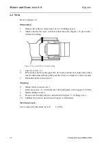
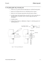
Страница 193: ...Installation and Commissioning On Site Installation Product Manual IRB 6400R 23 Figure 17 Cutting the cam Remove 90 30 ...
Страница 196: ...On Site Installation Installation and Commissioning 26 Product Manual IRB 6400R ...
Страница 270: ...Installing the Control Program Installation and Commissioning 100 Product Manual IRB 6400R ...
Страница 292: ...Maintenance CONTENTS Page 2 Product Manual IRB 6400R ...
Страница 299: ...Maintenance Product Manual IRB 6400R 9 Figure 4 Lubricating gearbox axis 1 4 3 1 2 ...
Страница 312: ...Troubleshooting Tools CONTENTS Page 2 Product Manual ...
Страница 350: ...Troubleshooting Tools 40 Product Manual ...
Страница 352: ...Fault tracing guide 2 Product Manual ...
Страница 362: ...Fault tracing guide 12 Product Manual ...
Страница 375: ...Motor units Repairs 12 Product Manual IRB 6400R ...
Страница 401: ...Arm System Repairs 38 Product Manual IRB 6400R ...
Страница 409: ...Cabling Repairs 46 Product Manual IRB 6400R ...
Страница 441: ...Special Tools List Repairs 80 Product Manual IRB 6400R ...
Страница 479: ...Part List and Spare Parts Product Manual IRB 6400R 38 ...
Страница 480: ...Part List and Spare Parts Product Manual IRB 6400R 39 ...
Страница 481: ...Part List and Spare Parts Product Manual IRB 6400R 40 ...


