background image

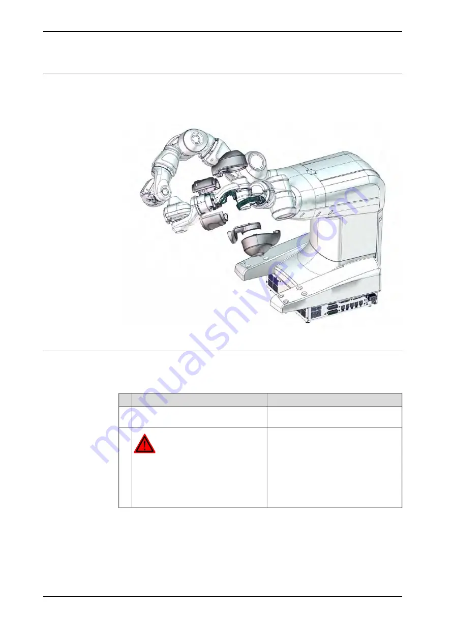
Covers to be removed for access

This figure shows an overview of which covers to remove to get access to the
spare part. Detailed instructions of how to remove the covers are found in the
removal procedure.

xx1500000491

Removing the hall sensor

Use these procedures to remove the hall sensor.

Preparations before removing the hall sensor

Note

Action

Jog the robot so that the covers can be
easily accessed and removed.

1

DANGER

Turn off all:

electric power supply

air pressure supply

to the robot, before starting the repair work
on the robot.

2

Continues on next page

256

Product manual - IRB 14000

3HAC052983-001 Revision: D

© Copyright 2015 - 2016 ABB. All rights reserved.

4 Repair

4.5.4 Replacing the axis-3 hall sensor

Continued

Содержание IRB 14000

Страница 1: ...Product manual IRB 14000 ...

Страница 2: ...Trace back information Workspace R16 2 version a5 Checked in 2016 09 08 Skribenta version 4 6 318 ...

Страница 3: ...Product manual IRB 14000 0 5 0 5 IRC5 Document ID 3HAC052983 001 Revision D Copyright 2015 2016 ABB All rights reserved ...

Страница 4: ...r property fitness for a specific purpose or the like In no event shall ABB be liable for incidental or consequential damages arising from use of this manual and products described herein This manual and parts thereof must not be reproduced or copied without ABB s written permission Additional copies of this manual may be obtained from ABB The original language for this publication is English Any ...

Страница 5: ...Pendant 39 1 2 5 7 Work inside the working range of the robot 40 1 2 5 8 Signal lamp optional 41 1 2 6 Safety stops 41 1 2 6 1 What is an emergency stop 42 1 2 6 2 What is a safety stop or protective stop 43 1 2 6 3 What is Cartesian speed supervision 44 1 3 Safety signals and symbols 44 1 3 1 Safety signals in the manual 46 1 3 2 Safety symbols on product labels 52 1 4 Safety related instructions...

Страница 6: ...ivities 126 3 5 1 Cleaning the IRB 14000 127 4 Repair 127 4 1 Introduction 128 4 2 General procedures 128 4 2 1 Mounting instructions for seals 130 4 3 Arm and arm covers 130 4 3 1 Replacing the complete arm 145 4 3 2 Replacing the encapsulation and covers 148 4 4 Motors 148 4 4 1 Replacing the axis 1 motor 149 4 4 2 Replacing the axis 2 motor 171 4 4 3 Replacing the axis 7 motor 172 4 4 4 Replaci...

Страница 7: ...lease harness 409 4 8 1 Replacing the brake release harness 417 5 Calibration 417 5 1 Introduction 418 5 2 Calibration method 419 5 3 Calibration scale and correct axis position 420 5 4 Calibrating the robot 428 5 5 Updating revolution counters 434 5 6 Calibration movement directions for all axes 435 5 7 Verifying the calibration position 437 6 Decommissioning 437 6 1 Introduction 438 6 2 Environm...

Страница 8: ...This page is intentionally left blank ...

Страница 9: ... installation or service work on robot Contains general safety aspects as well as more specific information on how to avoid personal injuries and damage to the product Safety service Required information about lifting and installation of the robot Installation and commis sioning Step by step procedures that describe how to perform mainten ance of the robot Based on a maintenance schedule that may ...

Страница 10: ...hnical reference manual System parameters i This manual contains all safety instructions from the product manuals for the manipulators and the controllers Revisions Description Revision First edition The following updates are done in this revision Minor editorial changes Changed article number for the ESD warning label and added AbsAcc label see Inspecting the information labels on page 111 Added ...

Страница 11: ...0 before running fine calibration procedure B The following updates are done in this revision Figures in procedures about Fitting the wave generator to the motor are updated Grease name and volume is moved to Manual Lubrication in gearboxes Specification of screws added to section Reference information Screw nut type and tightening torque added to steps in section Repair Plastic parts are ESD coat...

Страница 12: ...ration Decommissioning Reference information safety standards unit conversions screw joints lists of tools Spare parts list with exploded views or references to separate spare parts lists Circuit diagrams or references to circuit diagrams Technical reference manuals The technical reference manuals describe reference information for robotics products Technical reference manual Lubrication in gearbo...

Страница 13: ...plication Operating manuals The operating manuals describe hands on handling of the products The manuals are aimed at those having first hand operational contact with the product that is production cell operators programmers and trouble shooters The group of manuals includes among others Operating manual Emergency safety information Operating manual General safety information Operating manual Gett...

Страница 14: ...include specific safety information when dangerous steps are to be performed Read more in the chapter Safety on page 17 Illustrations The product is illustrated with general figures that does not take painting or protection type in consideration Likewise certain work methods or general information that is valid for several product models can be illustrated with illustrations that show a different ...

Страница 15: ...on of firewalls application of authentication measures encryption of data installation of anti virus programs etc to protect the product the network its system and the interface against any kind of security breaches unauthorized access interference intrusion leakage and or theft of data or information ABB Ltd and its entities are not liable for damages and or losses related to such security breach...

Страница 16: ...This page is intentionally left blank ...

Страница 17: ...18 Safety signals and symbols shown in the manual and on the robot warning for different types of dangers are found in Safety signals and symbols on page 44 Specific safety information pointed out in the procedures How to avoid and eliminate the danger is either described directly in the procedure or in specific instructions in the section Safety related instructions on page 52 Product manual IRB ...

Страница 18: ...ing installation or service risks associated with live electrical parts Safety risks lists dangers relevant when working with the product The dangers are split into different categories fire extinguishing safe use of the teach pendant or jogging device Safety actions describes actions which may be taken to remedy or avoid dangers stopping functions description of emergency stop description of safe...

Страница 19: ... system shall be designed and constructed in such a way as to allow safe access to all areas where intervention is necessary during operation adjustment and maintenance Users shall not be exposed to hazards including slipping tripping and falling hazards Connection of external safety devices Apart from the built in safety functions the robot is also supplied with an interface for the connection of...

Страница 20: ... according to EN ISO 13849 1 Description Safety function The Cartesian speed of the elbow arm check point ACP and the wrist wrist center point WCP are supervised If a limit is exceeded the robot motion is stopped and a message dis played to the user The default speed limit can be modified based on the risk assessment of the robot installation Cartesian speed supervi sion The function is active in ...

Страница 21: ...n If the risk assessment of the completed system concludes that there are risks relating to work pieces or end effectors then the speed limits must be lowered or the application must be redesigned See ISO 10218 2 Product manual IRB 14000 21 3HAC052983 001 Revision D Copyright 2015 2016 ABB All rights reserved 1 Safety 1 2 3 Safety in collaborative operation Continued ...

Страница 22: ...ssociated with it Spare parts and special equipment ABB does not supply spare parts and special equipment which have not been tested and approved by ABB The installation and or use of such products could negatively affect the structural properties of the robot and as a result of that affect the active or passive safety operation ABB is not liable for damages caused by the use of non original spare...

Страница 23: ...ng the axis 2 motor Removed parts may result in collapse of the robot WARNING If the internal cables for the measurement system have been disconnected during repair or maintenance then the revolution counters must be updated Removed cables to the measurement sys tem Cabling Description Safety risk CAUTION The cable packages are sensitive to mechan ical damage Handle the cable packages and the conn...

Страница 24: ...et hot and may result in burns Elimination The following instructions describe how to avoid the dangers specified above Information Action Always use your hand at some distance to feel if heat is radiating from the potentially hot component before actually touching it 1 Wait until the potentially hot component has cooled if it is to be removed or handled in any other way 2 24 Product manual IRB 14...

Страница 25: ...bot and operators is safe End tools such as fingers and suction tools as well as work pieces handled by the robot must be designed and chosen so that such contacts does not introduce safety hazards The IRB 14000 gripper is not designed to retain work pieces in case of power loss Objects held by the servo and vacuum modules may be released in the event of pneumatic or electric power loss to the gri...

Страница 26: ...sure released before installing or servicing the gripper The air pressure supplied to the robot and gripper must not exceed the rated limit Use pressure relief valves All pipes hoses and connections have to be inspected regularly for leaks and damage Damages must be repaired immediately Wear safety glasses when working with the pneumatic systems 26 Product manual IRB 14000 3HAC052983 001 Revision ...

Страница 27: ...sks The pressure relief valve is a vital part preventing too much air pressure being built up inside the robot If too much air pressure has been built up there is a risk of personal injury and mechanical damage Product manual IRB 14000 27 3HAC052983 001 Revision D Copyright 2015 2016 ABB All rights reserved 1 Safety 1 2 4 5 Safety risks with pressure relief valve ...

Страница 28: ...ntenance must only be carried out by qualified personnel who are familiar with the entire installation as well as the special risks associated with its different parts Extraordinary risks If the working process is interrupted extra care must be taken due to risks other than those associated with regular operation Such an interruption may have to be rectified manually 28 Product manual IRB 14000 3H...

Страница 29: ...el on machine robot system in deadlock in an isolated state disconnected from power supply and protected against reconnection Voltage related risks IRC5 controller A danger of high voltage is associated with for example the following parts Be aware of stored electrical energy DC link Ultracapacitor bank unit in the controller Units such as I O modules can be supplied with power from an external so...

Страница 30: ... robot arm Voltage related risks tools material handling devices etc Tools material handling devices etc may be live even if the robot system is in the OFF position Power supply cables which are in motion during the working process may be damaged 30 Product manual IRB 14000 3HAC052983 001 Revision D Copyright 2015 2016 ABB All rights reserved 1 Safety 1 2 4 7 Risks associated with live electric pa...

Страница 31: ...fitted to the tool flange Safe design of the robot cell Special attention in risk assessment must be given to the following parts end effectors fingers suction tools designed for the application work pieces handled by the robot in the application any custom gripping solutions that are selected for the application Product manual IRB 14000 31 3HAC052983 001 Revision D Copyright 2015 2016 ABB All rig...

Страница 32: ...hing Note Use a CARBON DIOXIDE CO2 extinguisher in the event of a fire in the robot system robot or controller 32 Product manual IRB 14000 3HAC052983 001 Revision D Copyright 2015 2016 ABB All rights reserved 1 Safety 1 2 5 1 Fire extinguishing ...

Страница 33: ...ly releasing the brakes on page 77 The robot arm may be moved manually on smaller robot models but larger models may require using an overhead crane or similar equipment Increased injury There are no safety risks when releasing the brakes the robot has the highest priority of safety Product manual IRB 14000 33 3HAC052983 001 Revision D Copyright 2015 2016 ABB All rights reserved 1 Safety 1 2 5 2 E...

Страница 34: ...o stop the motion of the arm If the arm is at standstill motors or brakes can be overridden To prevent unnecessary damage and wear to the robot arm it is strongly recommended to use the normal stopping functions of the control system and push the brake release buttons before manually moving the arm 34 Product manual IRB 14000 3HAC052983 001 Revision D Copyright 2015 2016 ABB All rights reserved 1 ...

Страница 35: ...as described below 1 Run each robot axis to a position where the combined weight of the robot arm and any load is maximized maximum static load 2 Switch the motor to the MOTORS OFF 3 Inspect and verify that the axis maintains its position If the robot does not change position as the motors are switched off then the brake function is adequate Product manual IRB 14000 35 3HAC052983 001 Revision D Co...

Страница 36: ...io or other kinematic system parameters from the FlexPendant or a PC This will affect the safety function Reduced speed 250 mm s 36 Product manual IRB 14000 3HAC052983 001 Revision D Copyright 2015 2016 ABB All rights reserved 1 Safety 1 2 5 5 Risk of disabling function Reduced speed 250 mm s ...

Страница 37: ... become a tripping hazard Never use sharp objects such as screwdriver or pen for operating the touch screen This could damage the touch screen Instead use your finger or a stylus located on the back on FlexPendant with USB port Clean the touch screen regularly Dust and small particles can clog the touch screen and cause it to malfunction Never clean the FlexPendant with solvents scouring agent or ...

Страница 38: ...e is of a specific type where you must press the push button only half way to activate it In the fully in and fully out positions operating the robot is impossible Note To ensure safe use of the jogging device the following must be implemented The enabling device must never be rendered inoperational in any way During programming and testing the enabling device must be released as soon as there is ...

Страница 39: ...ailable in USA or Canada Pay attention to the rotating axes of the robot Keep away from axes to not get entangled with hair or clothing Also be aware of any danger that may be caused by rotating tools or other devices mounted on the robot or inside the cell Test the motor brake on each axis according to the section Brake testing on page 35 To prevent anyone else from taking control of the robot al...

Страница 40: ...y device Function The lamp is active in MOTORS ON mode Further information Further information about the MOTORS ON MOTORS OFF mode may be found in the product manual for the controller 40 Product manual IRB 14000 3HAC052983 001 Revision D Copyright 2015 2016 ABB All rights reserved 1 Safety 1 2 5 8 Signal lamp optional ...

Страница 41: ...ergency stop function may only be used for the purpose and under the conditions for which it is intended Note The emergency stop function is intended for immediately stopping equipment in the event of an emergency Note Emergency stop should not be used for normal program stops as this causes extra unnecessary wear on the robot For how to perform normal program stops see section Stopping programs i...

Страница 42: ...egory 0 stop immediately stopping the robot actions by disconnecting power from the motors Note The safety stop function may only be used for the purpose and under the conditions for which it is intended Note Safety stop should not be used for normal program stops as this causes extra unnecessary wear on the manipulator For how to perform normal program stops see section Stopping programs in Opera...

Страница 43: ...n be modified if needed based on the risk assessment for the robot installation If any of the configured speed limits are exceeded then the robot motion is stopped and a message is displayed to the user The Cartesian speed supervision is active in both manual and automatic mode The setting is defined by system parameters Product manual IRB 14000 43 3HAC052983 001 Revision D Copyright 2015 2016 ABB...

Страница 44: ...ccur if the instructions are not followed that can lead to serious injury pos sibly fatal and or great damage to the product It applies to warnings that apply to danger with for example contact with high voltage electrical units explosion or fire risk risk of poisonous gases risk of crushing impact fall from height etc WARNING xx0100000002 Warns for electrical hazards which could result in severe ...

Страница 45: ...OTE xx0100000004 Describes where to find additional information or how to do an operation in an easier way TIP xx0100000098 Product manual IRB 14000 45 3HAC052983 001 Revision D Copyright 2015 2016 ABB All rights reserved 1 Safety 1 3 1 Safety signals in the manual Continued ...

Страница 46: ...lish German and French Symbols on safety labels Description Symbol Warning xx0900000812 Warns that an accident may occur if the instructions are not followed that can lead to serious injury possibly fatal and or great damage to the product It applies to warnings that apply to danger with for example contact with high voltage electrical units explosion or fire risk risk of poisonous gases risk of c...

Страница 47: ...Do not disassemble xx0900000815 Disassembling this part can cause injury Extended rotation xx0900000814 This axis has extended rotation working area compared to standard Brake release xx0900000808 Pressing this button will release the brakes This means that the robot arm can fall down Continues on next page Product manual IRB 14000 47 3HAC052983 001 Revision D Copyright 2015 2016 ABB All rights re...

Страница 48: ...t securely fastened xx1500002402 Crush xx0900000817 Risk of crush injuries Heat xx0900000818 Risk of heat that can cause burns Continues on next page 48 Product manual IRB 14000 3HAC052983 001 Revision D Copyright 2015 2016 ABB All rights reserved 1 Safety 1 3 2 Safety symbols on product labels Continued ...

Страница 49: ...00001141 1 2 3 4 xx1500002616 Brake release buttons xx0900000820 xx1000001140 Lifting bolt xx0900000821 Continues on next page Product manual IRB 14000 49 3HAC052983 001 Revision D Copyright 2015 2016 ABB All rights reserved 1 Safety 1 3 2 Safety symbols on product labels Continued ...

Страница 50: ...lowed Mechanical stop xx0900000824 No mechanical stop xx1000001144 Stored energy xx0900000825 Warns that this part contains stored energy Used in combination with Do not disassemble symbol Continues on next page 50 Product manual IRB 14000 3HAC052983 001 Revision D Copyright 2015 2016 ABB All rights reserved 1 Safety 1 3 2 Safety symbols on product labels Continued ...

Страница 51: ...re level Shut off with handle xx0900000827 Use the power switch on the controller Do not step xx1400002648 Warns that stepping on these parts can cause damage to the parts Product manual IRB 14000 51 3HAC052983 001 Revision D Copyright 2015 2016 ABB All rights reserved 1 Safety 1 3 2 Safety symbols on product labels Continued ...

Страница 52: ...e all emergency stop equipment is cor rectly installed and connected 1 How to use the hold to run function is de scribed in section How to use the hold to run function in the Operating manual IRC5 with FlexPendant Usually the hold to run function is active only in manual full speed mode To in crease safety it is also possible to activate hold to run for manual reduced speed with a system parameter...

Страница 53: ...ve all service tools and foreign objects from the robot and its working area 1 Verify that the robot is secured to its position see installation section in the product manual for the robot 2 Verify that the fixture and work piece are well secured if applicable 3 Verifiy that all arm covers and paddings are properly secured to the robot 4 Pay special attention to the function of the part that previ...

Страница 54: ...er severe injuries To avoid these dangers do not proceed working before eliminating the danger as detailed below Elimination Controller Note illustration Action xx1500000503 Switch off the main switch on the controller 1 A Main switch 54 Product manual IRB 14000 3HAC052983 001 Revision D Copyright 2015 2016 ABB All rights reserved 1 Safety 1 4 3 DANGER Make sure that the main power has been switch...

Страница 55: ...n Wrist straps must be tested frequently to ensure that they are not damaged and are operating cor rectly Use a wrist strap 1 The mat must be grounded through a current limit ing resistor Use an ESD protective floor mat 2 The mat should provide a controlled discharge of static voltages and must be grounded Use a dissipative table mat 3 Location of wrist strap button The location of the wrist strap...

Страница 56: ...fire may follow depending upon the circumstances Note Appropriate disposal regulations must be observed Elimination Note Action Operating temperatures are listed in Pre install ation procedure on page 60 Do not short circuit recharge puncture incinerate crush immerse force discharge or expose to temperatures above the declared operating temperature range of the product Risk of fire or explosion 1 ...

Страница 57: ...cription Warning Make sure that protective gear like goggles and gloves are al ways worn during this activity Changing and draining gearbox oil or grease may require hand ling hot lubricant heated up to 90 C xx0100000002 Hot oil or grease Make sure that protective gear like goggles and gloves are al ways worn When working with gearbox lub ricant there is a risk of an allergic reaction xx0100000002...

Страница 58: ...f the gearbox When changing the lubricant the amount refilled may differ from the specified amount depending on how much has previously been drained from the gearbox xx0100000004 Specified amount de pends on drained volume When draining the oil make sure that as much oil as possible is drained from the gearbox The reason for this is to drain as much oil sludge and metal chips as possible from the ...

Страница 59: ...portant that all safety information is observed There are general safety aspects that must be read through as well as more specific safety information that describes the danger and safety risks when performing the procedures Read the chapter Safety on page17 before performing any installation work Note If the IRB 14000 is connected to power always make sure that the robot is connected to protectiv...

Страница 60: ...found 3 Clean the unit with a lint free cloth if necessary 4 Make sure that the lifting accessory used is suitable to handle the weight of the robot as specified in Weight robot on page 61 5 If the robot is not installed directly it must be stored as described in Storage condi tions robot on page 62 6 Make sure that the expected operating environment of the robot conforms to the specifications as ...

Страница 61: ...e X plane Tx Bending torque in the Z plane Tz The table shows the various forces and torques working on the robot during different kinds of operation Note These forces and torques are extreme values that are rarely encountered during operation The values also never reach their maximum at the same time Table mounted Max load emergency stop Endurance load in operation Force 178 N 89 N Force x 294 N ...

Страница 62: ...t Contact ABB for further information about accept able loads 22Hz Minimum resonance frequency Storage conditions robot The table shows the allowed storage conditions for the robot Value Parameter 10 C Minimum ambient temperature 55 C Maximum ambient temperature 55 C Maximum ambient temperature less than 24 hrs 85 at constant temperature gaseous only Maximum ambient humidity Operating conditions r...

Страница 63: ...ith the corresponding protection class Protection class Protection type IP30 Manipulator protection type Standard Product manual IRB 14000 63 3HAC052983 001 Revision D Copyright 2015 2016 ABB All rights reserved 2 Installation and commissioning 2 2 1 Pre installation procedure Continued ...

Страница 64: ...sions IRB 14000 470 360 421 187 5 305 220 96 399 260 C L 75 571 xx1500000103 64 Product manual IRB 14000 3HAC052983 001 Revision D Copyright 2015 2016 ABB All rights reserved 2 Installation and commissioning 2 2 2 Dimensions ...

Страница 65: ... the unrestricted working range of the robot Front view 0 347 593 1018 94 0 14 451 235 664 Z Y xx1500000105 Continues on next page Product manual IRB 14000 65 3HAC052983 001 Revision D Copyright 2015 2016 ABB All rights reserved 2 Installation and commissioning 2 2 3 Working range ...

Страница 66: ...1500000660 Top view 0 14 451 235 664 0 53 60 274 680 8 405 X Y xx1500000336 Continues on next page 66 Product manual IRB 14000 3HAC052983 001 Revision D Copyright 2015 2016 ABB All rights reserved 2 Installation and commissioning 2 2 3 Working range Continued ...

Страница 67: ... 2 168 5 to 168 5 Arm Rotation motion Axis 7 123 5 to 80 Arm Bend motion Axis 3 290 to 290 Wrist Rotation motion Axis 4 88 to 138 Wrist Bend motion Axis 5 229 to 229 Flange Rotation motion Axis 6 Product manual IRB 14000 67 3HAC052983 001 Revision D Copyright 2015 2016 ABB All rights reserved 2 Installation and commissioning 2 2 3 Working range Continued ...

Страница 68: ...ost stable position Do not change the robot position before securing it to the foundation Shipping and transport position This figure shows the robot in its shipping position which also is a recommended transport position xx1500000625 WARNING The robot is likely to be mechanically unstable if not secured to the foundation 68 Product manual IRB 14000 3HAC052983 001 Revision D Copyright 2015 2016 AB...

Страница 69: ...53 Required equipment Note Article number Equipment etc Overhead crane 38 kg capacity of lifting chain Lifting chain Lifting eye M8 DIN580 Lifting the robot Use the following procedure to lift the robot Note Action CAUTION The IRB 14000 robot weighs 38 kg All lifting accessories used must be sized ac cordingly 1 Continues on next page Product manual IRB 14000 69 3HAC052983 001 Revision D Copyright...

Страница 70: ...M8 DIN580 xx1500000626 Fit the lifting eye to the robot 4 Attach the lifting chain to the lifting eye and to the overhead crane 5 Carefully stretch the chain by lifting the crane slowly 6 Screw 8 pcs of M5x25 Remove the robot attachment screws if the robot is fastened 7 Continues on next page 70 Product manual IRB 14000 3HAC052983 001 Revision D Copyright 2015 2016 ABB All rights reserved 2 Instal...

Страница 71: ...e the overhead crane to lift the robot 8 Product manual IRB 14000 71 3HAC052983 001 Revision D Copyright 2015 2016 ABB All rights reserved 2 Installation and commissioning 2 3 1 Lifting the robot with lifting accessories Continued ...

Страница 72: ... torque 0 1 xx1500000627 Level surface requirements Lifting and transporting the robot Use this procedure to lift the robot Note Action CAUTION The IRB 14000 robot weighs 38 kg and can be lifted by two persons 1 xx1400002122 Grasp the hand holding grooves one person on each side of the robot 2 Continues on next page 72 Product manual IRB 14000 3HAC052983 001 Revision D Copyright 2015 2016 ABB All ...

Страница 73: ...ng the robot This could damage the mechanical structure of the arm 4 Screws 8 pcs M5x25 Secure the robot on a workbench according to section Orienting and securing the robot on page 74 5 Washers 8 pcs 5 3x10x1 xx1400002021 Product manual IRB 14000 73 3HAC052983 001 Revision D Copyright 2015 2016 ABB All rights reserved 2 Installation and commissioning 2 3 2 Lifting the robot by two persons Continu...

Страница 74: ...ds on foundation robot on page 61 Hole configuration base There are eight holes on the bottom of the robot body 0 0 40 40 162 143 162 124 143 124 0 3 0 06 58 1 0 6Thru 8x 1 98 0 2x 6 6 m6 2x 6 H8 12 24 12 2 A 2x 0 06 C C C C B B 10 8x 10 5 8x 6 0 3 0 3 B B xx1400002124 Continues on next page 74 Product manual IRB 14000 3HAC052983 001 Revision D Copyright 2015 2016 ABB All rights reserved 2 Install...

Страница 75: ...ies the type of securing screws to be used to secure the robot directly to the foundation It also specifies the type of pins to be used M5x25 Screws 8 pcs Quantity 8 8 Quality 8 pcs 5 3x10x1 Washer 2 pcs article number 3HNP00449 1 Guide pins 3 8 Nm 0 38 Nm Tightening torque Continues on next page Product manual IRB 14000 75 3HAC052983 001 Revision D Copyright 2015 2016 ABB All rights reserved 2 In...

Страница 76: ...robot by two per sons on page 72 Lifting the robot with lifting accessories on page 69 Lift the robot to its installation site CAUTION Be careful not to hit the arms into something while lifting and transporting the robot This could damage the mechanical structure of the arm 5 2 pcs article number 3HNP00449 1 Make sure there are two pins in the holes in the base 6 Make sure the robot base is cor r...

Страница 77: ...ng brake for axis 4 axis 5 or axis 6 Location of brake release button There are two brake release buttons located as shown in the figure xx1400002126 Brake release button for right arm A Brake release button for left arm B Continues on next page Product manual IRB 14000 77 3HAC052983 001 Revision D Copyright 2015 2016 ABB All rights reserved 2 Installation and commissioning 2 3 4 Manually releasin...

Страница 78: ...lied to the robot see Connecting power and the FlexPendant on page 90 1 CAUTION When releasing the holding brakes the robot axes may move very quickly and sometimes in unexpec ted ways 2 Release the holding brake on the right arm axes by pressing the button A 3 Release the holding brake on the left arm axes by pressing the button B The brake will function again as soon as the button A or B is rele...

Страница 79: ...ON Incorrectly defined loads may result in operational stops or major damage to the robot References Load diagrams permitted extra loads equipment and their positions are specified in the product specification The loads must also be defined in the software as detailed in Operating manual IRC5 with FlexPendant Product manual IRB 14000 79 3HAC052983 001 Revision D Copyright 2015 2016 ABB All rights ...

Страница 80: ...ws the user to meet UL requirements Location of signal lamp The signal lamp is located as shown in the figure xx1500000051 Required parts Note Article number Spare part Includes attachment screws 3HAC053350 001 Signal lamp M2x8 8 8 3HAC050368 005 Hex socket head cap screw M3x12 8 8 Gleitmo 605 3HAC050367 005 Torx pan head screw Continues on next page 80 Product manual IRB 14000 3HAC052983 001 Revi...

Страница 81: ...vers Note Action DANGER Make sure that all supplies for electrical power and air pressure are turned off 1 xx1400002904 Remove the body cover top screws 2 xx1500000303 Remove the body cover 3 Continues on next page Product manual IRB 14000 81 3HAC052983 001 Revision D Copyright 2015 2016 ABB All rights reserved 2 Installation and commissioning 2 3 6 Installing the signal lamp Continued ...

Страница 82: ...1500000564 5 Installing the signal lamp Note Action DANGER Make sure that all supplies for electrical power hy draulic pressure and air pressure are turned off 1 xx1500000605 Remove the protection cover 2 Continues on next page 82 Product manual IRB 14000 3HAC052983 001 Revision D Copyright 2015 2016 ABB All rights reserved 2 Installation and commissioning 2 3 6 Installing the signal lamp Continue...

Страница 83: ...Refitting the body covers Note Action Screws 3HAC050368 005 5 pcs Refit the front and lower body cover Note Be aware of the tab underneath the cover so it does not get damaged xx1500000564 1 Tightening torque 0 2 Nm xx1400002603 Continues on next page Product manual IRB 14000 83 3HAC052983 001 Revision D Copyright 2015 2016 ABB All rights reserved 2 Installation and commissioning 2 3 6 Installing ...

Страница 84: ... body cover 3 Tightening torque 0 9 Nm xx1500000697 Screws 3HAC050367 005 2 pcs Refit the two remaining screws of the body cover 4 Tightening torque 0 2 Nm xx1500000696 Continues on next page 84 Product manual IRB 14000 3HAC052983 001 Revision D Copyright 2015 2016 ABB All rights reserved 2 Installation and commissioning 2 3 6 Installing the signal lamp Continued ...

Страница 85: ...he body cover top screws 5 Tightening torque 0 2 Nm xx1400002904 Product manual IRB 14000 85 3HAC052983 001 Revision D Copyright 2015 2016 ABB All rights reserved 2 Installation and commissioning 2 3 6 Installing the signal lamp Continued ...

Страница 86: ... provided by customer or purchased from ABB as option The following table lists the ABB supplied main power cables in different interface standards Choose as required Article number Spare part 3HAC056583 001 Mains cable with locking system EU 2m 3HAC056583 002 Mains cable with locking system UK 2m 3HAC056583 003 Mains cable with locking system US 6ft 3HAC056583 004 Mains cable with locking system ...

Страница 87: ...in the controller report the following data to ABB for both the replaced unit and the replacement unit the serial number article number revision This is particularly important for the safety equipment to maintain the safety integrity of the installation Continues on next page Product manual IRB 14000 87 3HAC052983 001 Revision D Copyright 2015 2016 ABB All rights reserved 2 Installation and commis...

Страница 88: ...n number 9 24 V max current 3A Digital outputs XS7 8 digital output signals 150 mA channel from the internal I O board DSQC 652 Pin number 9 24 V max current 3A Service XP23 WAN connection to factory WAN XP28 LAN2 connection of Ethernet based options XP25 LAN3 connection of Ethernet based options XP26 FA Fieldbus adapter XP11 PROFINET or EtherNet IP fieldbus adapter option USB port to main compute...

Страница 89: ... panel of the controller xx1400002125 Power switch Q1 FlexPendant XS4 Power input XP0 Main AC power connector IEC 60320 1 C14 100 240 VAC 50 60 Hz Product manual IRB 14000 89 3HAC052983 001 Revision D Copyright 2015 2016 ABB All rights reserved 2 Installation and commissioning 2 4 1 Overview Continued ...

Страница 90: ...s 5A at 100 240 V Rated power Rated power of the IRB 14000 is 360 W Required equipment Note Equipment Power supply cable single phase 8A External circuit breaker 30mA External earth fault protection at control cables 3 15m 300mA External earth fault protection at control cables 15m See Circuit diagram IRB 14000 Circuit diagram Continues on next page 90 Product manual IRB 14000 3HAC052983 001 Revis...

Страница 91: ...te the main AC power connector on the right side of the controller 1 Connect the power cable 2 Connecting a FlexPendant The following procedure describes how to connect a FlexPendant to the controller CAUTION Always inspect the connector for dirt or damage before connecting it to the controller Clean or replace any damaged parts Information Action The controller must be in manual mode Locate the F...

Страница 92: ...ice XP23 WAN connection to factory WAN XP28 LAN2 connection of Ethernet based options XP25 LAN3 connection of Ethernet based options XP26 USB port to main computer XP24 Multiple Ethernet based options For IRB 14000 it is possible to use both the options PROFINET Controller Device 888 2 and EtherNet IP Scanner Adapter 841 1 at the same time Continues on next page 92 Product manual IRB 14000 3HAC052...

Страница 93: ... X6 Panel unit X7 blue Axis computer X9 red USB ports 4 ports X10 X11 Note It is not supported to connect multiple ports of the main computer X2 X6 to the same external switch unless static VLAN isolation is applied on the external switch Service port The service port is intended for service engineers and programmers connecting directly to the controller with a PC Continues on next page Product ma...

Страница 94: ...cannot use any of the following IP addresses which are allocated for other functions on the IRC5 controller 192 168 125 0 255 192 168 126 0 255 192 168 127 0 255 192 168 128 0 255 192 168 129 0 255 192 168 130 0 255 The WAN port cannot be on a subnet which overlaps with any of the above reserved IP addresses If a subnet mask in the class B range has to be used then a private address of class B mus...

Страница 95: ...y for RobotWare 6 01 and later The default configuration is that LAN 3 is configured as an isolated network This allows LAN 3 to be connected to an external network including other robot controllers The isolated LAN 3 network has the same address limitations as the WAN network WAN LAN 2 LAN 3 Private Robot Controller LAN 1 Service Public Isolated LAN 3 xx1500000393 An alternative configuration is ...

Страница 96: ...e intended for connecting USB memory devices Note It is recommended to use the USB ports USB1 and USB2 on the X10 connector for connecting USB memory devices The USB ports on the X11 connector are intended for internal use 96 Product manual IRB 14000 3HAC052983 001 Revision D Copyright 2015 2016 ABB All rights reserved 2 Installation and commissioning 2 4 3 1 Connectors on the computer unit Contin...

Страница 97: ...ector for connecting digital I O signals instead 3UHSDUHG E GDWH H UHVHUYH DOO ULJKWV LQ WKLV GRFXPHQW DQG LQ WKH LQIRUPDWLRQ FRQWDLQHG WKHUHLQ 5HSURGXFWLRQ XVH RU GLVFORVXUH WR WKLUG SDUWLHV ZLWKRXW H SUHVV DXWKRULW LV VWULFWO IRUELGGHQ RS ULJKW DWHVW UHYLVLRQ SSURYHG E GDWH XVWRP DE 2IILFH 5 14 1 1 XVWRPHU LQWHUIDFH 2 6DIHW 9 9 9 9 7RRO 2 5 OWHUQDWLYH WR WKHUQHW WR 7RRO 3 6B 3 6B 3 6B 3 6B 3 6B5...

Страница 98: ... topic I O System with the names custom_DI_x and custom_DO_x The customer should change the names to fit the current application For more information about configuring I O see Application manual DeviceNet Master Slave and Technical reference manual System parameters 98 Product manual IRB 14000 3HAC052983 001 Revision D Copyright 2015 2016 ABB All rights reserved 2 Installation and commissioning 2 ...

Страница 99: ...egrated IRC5 main computer xx1400002129 DeviceNet XS17 Fieldbus adapter XS10 PROFIBUS fieldbus adapter option Fieldbus adapter XP11 PROFINET or EtherNet IP fieldbus adapter option Note DeviceNet m s option 709 1 is provided at XS17 as default The DeviceNet fieldbus adapter option 840 4 is not supported by IRB 14000 Continues on next page Product manual IRB 14000 99 3HAC052983 001 Revision D Copyri...

Страница 100: ... expansion board for fieldbus adapters without adapter A Fieldbus adapters The fieldbus adapters are inserted into the expansion board on top of the main computer unit There is one slot available for installing a fieldbus adapter A xx1300000604 Continues on next page 100 Product manual IRB 14000 3HAC052983 001 Revision D Copyright 2015 2016 ABB All rights reserved 2 Installation and commissioning ...

Страница 101: ...ssible The termination resistor is placed in the cable connector There is no internal termination on the DeviceNet PCI board The termination resistor is connected between CANL and CANH that is between pin 2 and pin 4 according to the illustration below xx0400000674 References For more information on how to install and configure the fieldbuses see the respective fieldbus application manual Product ...

Страница 102: ...afety devices The safety connector on the foot interface is plugged with a safety bridge connector that closes both emergency stop channels of the FlexPendant The safety stop input on each drive monitors this channel and triggers a safety stop if the circuit is open or not powered 4 XS XP4 5 6 3 XS XP9 1 2 3 4 5 6 7 8 24V 0V DSQC462 Drive board_Right arm 1 A51 DSQC462 Drive board_Left arm 2 A52 Fl...

Страница 103: ...ll Dual channel safety performance can be maintained where such is required IRB 14000 can be stopped from the safety PLC by routing back a single channel stop signal to the safety connector XS9 ES1 ES1 ES2 ES2 SDO SDO Safety PLC 4 XS XP4 5 6 3 XS XP9 1 2 3 4 5 6 7 8 24V 0V DSQC462 Drive board_Right arm 1 A51 DSQC462 Drive board_Left arm 2 A52 FlexPendant IRC5 controller xx1500000014 For more infor...

Страница 104: ...XS9 The safety relay also receives main power inputs and then feeds the inputs to the robot power inlet Contact ABB for further information xx1600001076 For more information about connecting the safety signals see Circuit diagram IRB 14000 104 Product manual IRB 14000 3HAC052983 001 Revision D Copyright 2015 2016 ABB All rights reserved 2 Installation and commissioning 2 4 6 Connecting safety sign...

Страница 105: ...ory containing ABB Boot Application software The SD card memory is located inside the computer unit Note Only use SD card memory supplied by ABB Product manual IRB 14000 105 3HAC052983 001 Revision D Copyright 2015 2016 ABB All rights reserved 2 Installation and commissioning 2 4 7 1 SD card memory ...

Страница 106: ...ntroller is shown by the following illustration xx1400002129 USB1 port to main computer XP24 Location on the FlexPendant The location of the USB port on the FlexPendant is shown by the following illustration xx1500000701 106 Product manual IRB 14000 3HAC052983 001 Revision D Copyright 2015 2016 ABB All rights reserved 2 Installation and commissioning 2 4 7 2 Connecting an USB memory ...

Страница 107: ...ections and divided according to the maintenance activity Safety information Observe all safety information before conducting any service work There are general safety aspects that must be read through as well as more specific safety information that describes the danger and safety risks when performing the procedures Read the chapter Safety on page 17 before performing any service work Note If th...

Страница 108: ...ing time specified in operating hours More frequent running means more frequent maintenance activities SIS specified by the robot s SIS Service Information System A typical value is given for a typical work cycle but the value will differ depending on how hard each part is run The SIS used in M2004 is further described in the Operating manual Service Information System 108 Product manual IRB 14000...

Страница 109: ... the robot Inspecting the information labels on page 111 x Inspecting the information labels Inspecting cable harness on page 117 x Inspecting cable harness Inspecting plastic and padding on page 119 x x ii Inspecting plastics and padding i Regularly implies that the activity is to be performed regularly but the actual interval may not be specified by the robot manufacturer The interval depends on...

Страница 110: ...ties and intervals Reference Every 12 months Maintenance activities Inspection activities Inspecting signal lamp on page 115 x Inspecting the signal lamp 110 Product manual IRB 14000 3HAC052983 001 Revision D Copyright 2015 2016 ABB All rights reserved 3 Maintenance 3 2 2 Maintenance schedule Continued ...

Страница 111: ...bels on page 46 A B lean warning lifting label calibration label calibration label read manual UL label rating label C VIEW C ESD warning C F G E L F D J H K AbsAcc xx1500000720 Illustration Description xx1500000723 Instruction plate Brake release A Continues on next page Product manual IRB 14000 111 3HAC052983 001 Revision D Copyright 2015 2016 ABB All rights reserved 3 Maintenance 3 3 1 Inspecti...

Страница 112: ... Caution label Risk of tipping D xx1500000727 Read manual label E Calibration label F Continues on next page 112 Product manual IRB 14000 3HAC052983 001 Revision D Copyright 2015 2016 ABB All rights reserved 3 Maintenance 3 3 1 Inspecting the information labels Continued ...

Страница 113: ...ble can be out of date See the latest revision of Product manual spare parts IRB 14000 on ABB Library Note Article number Spare part 3HAB9549 1 Rating label Electrical shock 3HAC1589 1 Warning sign Risk of tipping 3HAC053895 001 Caution label Disconnect power before servi cing controller 3HAC055245 001 Warning label Brake release 3HAC053898 001 Instruction plate 3HAC053978 001 Lifting label 3HAC05...

Страница 114: ...upply air pressure supply to the robot before starting maintenance acitivities 1 Inspect the labels located as shown in the figures 2 Replace any missing or damaged labels 3 114 Product manual IRB 14000 3HAC052983 001 Revision D Copyright 2015 2016 ABB All rights reserved 3 Maintenance 3 3 1 Inspecting the information labels Continued ...

Страница 115: ...gnal lamp Content is defined in section Stand ard toolkit on page 449 Standard toolkit Inspecting signal lamp Use this procedure to inspect the function of the signal lamp Note Action Verify that the signal lamp is lit when motors are put in operation MOTORS ON 1 Continues on next page Product manual IRB 14000 115 3HAC052983 001 Revision D Copyright 2015 2016 ABB All rights reserved 3 Maintenance ...

Страница 116: ...not lit trace the fault by Make sure that the signal lamp is not broken If so replace it Inspect the cable connections Inspect the cabling Replace the cabling if a fault is detected 3 For details about how to replace the signal lamp see Installing the signal lamp on page 80 116 Product manual IRB 14000 3HAC052983 001 Revision D Copyright 2015 2016 ABB All rights reserved 3 Maintenance 3 3 2 Inspec...

Страница 117: ...he tool flange In the figure below all covers required to be removed for visual access to the cable harness are removed xx1400002908 Required tools and equipment Note Article number Equipment etc Content is defined in section Standard toolkit on page 449 Standard toolkit Continues on next page Product manual IRB 14000 117 3HAC052983 001 Revision D Copyright 2015 2016 ABB All rights reserved 3 Main...

Страница 118: ... the complete robot arm Grease Mobil FM222 Inspect that the cabling is lubricated properly 4 If needed apply grease evenly on the moving part of the cable harness It is normal that the grease color turns into black Replacement information for the covers such as pare part numbers and tightening torques for the at tachment screws are detailed in section Replacing the encapsula tion and covers on pag...

Страница 119: ...of these parts are necessary Required tools and equipment Note Article number Equipment etc Content is defined in section Standard toolkit on page 449 Standard toolkit Inspecting plastic and padding Note Action DANGER Turn off all electric power supply air pressure supply to the robot before starting the inspection work on the robot 1 Continues on next page Product manual IRB 14000 119 3HAC052983 ...

Страница 120: ...otective function for other reasons it must be replaced 2 Tightening torques are specified in Replacing the encapsulation and covers on page 145 Make sure that all plastic and padding covers are fully fastened Manually check that the parts are not loose Tighten if needed 3 120 Product manual IRB 14000 3HAC052983 001 Revision D Copyright 2015 2016 ABB All rights reserved 3 Maintenance 3 3 4 Inspect...

Страница 121: ...n until the battery is to be replaced Location of battery pack The battery pack RMU is located as shown in the figure xx1500000504 Required spare parts Note The spare part numbers that are listed in the table can be out of date Contact ABB for the latest revision of Product manual spare parts IRB 14000 Continues on next page Product manual IRB 14000 121 3HAC052983 001 Revision D Copyright 2015 201...

Страница 122: ...facilitate updating of the revolution counter Move the robot to its calibration position 1 DANGER Turn off all electric power supply air pressure supply to the robot before starting the repair work on the robot 2 Removing the battery pack Note Action DANGER Make sure that all supplies for electrical power hydraulic pressure and air pressure are turned off 1 ELECTROSTATIC DISCHARGE ESD The unit is ...

Страница 123: ...00505 Disconnect the battery connector X3 4 Cut the cable tie that secures the battery and re move the battery 5 Continues on next page Product manual IRB 14000 123 3HAC052983 001 Revision D Copyright 2015 2016 ABB All rights reserved 3 Maintenance 3 4 1 Replacing the battery pack Continued ...

Страница 124: ...n page 55 1 xx1500000506 Fit the battery and and secure it with a cable tie Note Battery includes protection circuits Only replace with a specified spare part or with an ABB ap proved equivalent 2 xx1500000505 Connect the battery connector X3 3 Tightening torque 0 9 Nm xx1500000697 Refit the body cover 4 Continues on next page 124 Product manual IRB 14000 3HAC052983 001 Revision D Copyright 2015 2...

Страница 125: ...See Updating revolution counters on page 428 Update the revolution counters 1 CAUTION Make sure all safety requirements are met when performing the first test run These are further detailed in the section DANGER First test run may cause injury or damage on page 53 2 Product manual IRB 14000 125 3HAC052983 001 Revision D Copyright 2015 2016 ABB All rights reserved 3 Maintenance 3 4 1 Replacing the ...

Страница 126: ...t as specified above Any other cleaning equipment may shorten the life of the robot Always check that all protective covers are fitted to the robot before cleaning Never Never use compressed air to clean the robot Never use solvents that are not approved by ABB to clean the robot Never remove any covers or other protective devices before cleaning the robot Cleaning methods These following table de...

Страница 127: ...r activity are listed in the respective procedures The details of equipment are also available in different lists in the chapter Reference information on page 441 Safety information There are general safety information and specific safety information The specific safety information describes the danger and safety risks while performing specific steps in a procedure Make sure to read through the ch...

Страница 128: ...sure that The seal is of the correct type provided with cutting edge There is no damage to the sealing edge feel with a fingernail 1 Inspect the sealing surface before mounting If scratches or damage are found the seal must be replaced since it may result in future leakage 2 Article number is specified in Equipment on page128 Lubricate the seal with grease just before fitting Not too early there i...

Страница 129: ...preferably with a brush 3 Tighten the screws evenly when fastening the flange joint 4 O rings The following procedure describes how to fit o rings Note Action Ensure that the correct o ring size is used 1 Defective o rings may not be used Check the o ring for surface defects burrs shape accuracy and so on 2 Defective o rings may not be used Check the o ring grooves 3 The grooves must be geometrica...

Страница 130: ... Required spare parts Note The spare part numbers that are listed in the table can be out of date See the latest revision of Product manual spare parts IRB 14000 on ABB Library Continues on next page 130 Product manual IRB 14000 3HAC052983 001 Revision D Copyright 2015 2016 ABB All rights reserved 4 Repair 4 3 1 Replacing the complete arm ...

Страница 131: ...et head cap screw Required tools and equipment Note Article number Equipment etc Content is defined in section Standard toolkit on page 449 Standard toolkit Covers to be removed for access This figure shows an overview of which covers to remove to get access to the spare part Detailed instructions of how to remove the covers are found in the removal procedure xx1500000493 Continues on next page Pr...

Страница 132: ...ressure supply to the robot before starting the repair work on the robot 2 Removing the body covers Note Action DANGER Make sure that all supplies for electrical power and air pressure are turned off 1 xx1400002904 Remove the body cover top screws 2 Continues on next page 132 Product manual IRB 14000 3HAC052983 001 Revision D Copyright 2015 2016 ABB All rights reserved 4 Repair 4 3 1 Replacing the...

Страница 133: ... of the tab underneath the cover so it does not get damaged xx1500000564 5 Removing the axis 1 covers Note Action DANGER Make sure that all supplies for electrical power and air pressure are turned off 1 Continues on next page Product manual IRB 14000 133 3HAC052983 001 Revision D Copyright 2015 2016 ABB All rights reserved 4 Repair 4 3 1 Replacing the complete arm Continued ...

Страница 134: ...r 2 xx1400002605 xx1500000565 Remove the upper screws of the lower axis 1 cover 3 Continues on next page 134 Product manual IRB 14000 3HAC052983 001 Revision D Copyright 2015 2016 ABB All rights reserved 4 Repair 4 3 1 Replacing the complete arm Continued ...

Страница 135: ...ith cabling still connected Note Two persons working together are required to perform this procedure Note Action DANGER Make sure that all supplies for electrical power and air pressure are turned off 1 Continues on next page Product manual IRB 14000 135 3HAC052983 001 Revision D Copyright 2015 2016 ABB All rights reserved 4 Repair 4 3 1 Replacing the complete arm Continued ...

Страница 136: ...se the brakes and rotate axis 1 in or der to access all the screws Move the axes back into original position when all the screws are removed 4 DANGER Turn off the electric power supply again 5 xx1400002608 Remove the arm from the body CAUTION The cabling is still connected inside the robot be careful not to strain the cables 6 Continues on next page 136 Product manual IRB 14000 3HAC052983 001 Revi...

Страница 137: ...Remove all attachment screws that fasten the controller to the body 3 xx1500000365 Carefully pull the controller out partially in the rails so that the power and signal con nectors can be accessed CAUTION The controller weighs 13 kg Support the weight of the controller 4 Continues on next page Product manual IRB 14000 137 3HAC052983 001 Revision D Copyright 2015 2016 ABB All rights reserved 4 Repa...

Страница 138: ... together are required to perform this procedure Note Action Insert the cabling into the body while hold ing the arm 1 Screw 3HAB3409 232 6 pcs Refit the arm and secure with the screws 2 Tightening torque 3 Nm xx1400002608 Some of the screws might not be possible to refit until the cabling is reconnected to the controller and the brakes can be re leased Leave these screws for now CAUTION Be carefu...

Страница 139: ... A33 X3 A2 XSEN A2 XPCP Right side A51 XS11 12 17 13 14 15 16 A51 X3 A51 SMB X2 X4 X5 A33 X2 A1 XSEN A1 XPCP Connect the air hoses to the controller 2 Secure the cabling again with cable ties 3 Gently push the controller into the robot body completely CAUTION Be careful not to squeeze or damage the cables and air hoses in any way 4 Continues on next page Product manual IRB 14000 139 3HAC052983 001...

Страница 140: ...e body Note Action Turn on the power to the robot temporarily 1 Screw 3HAB3409 232 6 pcs Secure any remaining screws that fasten the arm to the body 2 Tightening torque 3 Nm xx1500000543 Release the brakes and rotate axis 1 in or der to access all the screws Turn off the electric power supply again 3 Continues on next page 140 Product manual IRB 14000 3HAC052983 001 Revision D Copyright 2015 2016 ...

Страница 141: ...t the lower axis 1 cover 1 Nuts 9ADA267 1 4 pcs Tightening torque 0 14 Nm xx1400002606 xx1400002604 Continues on next page Product manual IRB 14000 141 3HAC052983 001 Revision D Copyright 2015 2016 ABB All rights reserved 4 Repair 4 3 1 Replacing the complete arm Continued ...

Страница 142: ...te Action Screws 3HAC050368 005 5 pcs Refit the front and lower body cover Note Be aware of the tab underneath the cover so it does not get damaged xx1500000564 1 Tightening torque 0 2 Nm xx1400002603 Continues on next page 142 Product manual IRB 14000 3HAC052983 001 Revision D Copyright 2015 2016 ABB All rights reserved 4 Repair 4 3 1 Replacing the complete arm Continued ...

Страница 143: ...s Refit the body cover 3 Tightening torque 0 9 Nm xx1500000697 Screws 3HAC050367 005 2 pcs Refit the two remaining screws of the body cover 4 Tightening torque 0 2 Nm xx1500000696 Continues on next page Product manual IRB 14000 143 3HAC052983 001 Revision D Copyright 2015 2016 ABB All rights reserved 4 Repair 4 3 1 Replacing the complete arm Continued ...

Страница 144: ... Recalibrate the robot 1 CAUTION Make sure all safety requirements are met when performing the first test run These are further detailed in the section DANGER First test run may cause injury or damage on page 53 2 144 Product manual IRB 14000 3HAC052983 001 Revision D Copyright 2015 2016 ABB All rights reserved 4 Repair 4 3 1 Replacing the complete arm Continued ...

Страница 145: ...he cover attachment screws Tightening torque Covers that need to be removed for ac cess Description Spare part number 0 14 Nm Upper axis 1 cover ESD coated 3HAC057718 001 9ADA267 4 A Nut 0 14 Nm Upper axis 1 cover brake ESD coated 3HAC057719 001 9ADA267 4 B Nut Continues on next page Product manual IRB 14000 145 3HAC052983 001 Revision D Copyright 2015 2016 ABB All rights reserved 4 Repair 4 3 2 R...

Страница 146: ... Lower axis 3 cover ESD coated 3HAC050532 001 J 0 14 Nm Cover J Upper axis 3 cover ESD coated 3HAC050538 001 K 3HAC050532 001 Cover L 3HAC050542 001 Cover M 3HAC050535 001 0 14 Nm Lower axis 4 cover ESD coated 3HAC050542 001 L 0 14 Nm Cover J Axis 3 body cover ESD coated 3HAC050535 001 M 3HAC050532 001 Cover L 3HAC050542 001 0 14 Nm Cover L Axis 4 cable protection 3HAC049878 001 N 3HAC050542 001 C...

Страница 147: ...ooling flange with padding 3HAC041286 001 T 3HAC050548 001 Cover R 3HAC050553 001 CAUTION Make sure all safety requirements are met when performing the first test run These are further detailed in the section DANGER First test run may cause injury or damage on page 53 Required tools and equipment Note Article number Equipment etc Content is defined in section Standard toolkit on page 449 Standard ...

Страница 148: ...lete arm It is recommended to exchange the complete arm in case of a broken axis 1 motor See Replacing the complete arm on page 130 The axis 1 motor can be replaced by ABB contact your local ABB for more information 148 Product manual IRB 14000 3HAC052983 001 Revision D Copyright 2015 2016 ABB All rights reserved 4 Repair 4 4 1 Replacing the axis 1 motor ...

Страница 149: ... Article number Spare part Always use a new o ring 3HAB3772 137 To be ordered separately 3HAC036859 001 Motor M93 Required to be replaced when removing and refitting the motor 3HAB3772 137 O ring M4x16 12 9 Steel Black Oxide 3HAB3409 212 Hex socket head cap screw M2x8 8 8 3HAC050368 005 Hex socket head cap screw M2 DIN934 8 ELZN 9ADA267 1 Nut Continues on next page Product manual IRB 14000 149 3HA...

Страница 150: ...Consumable Mobil FM222 Grease Used to lubricate o rings Used to lubricate the wave generator Grease See Technical reference manual Lub rication in gearboxes Isopropanol Cleaning agent Required documents Note Document number Document name 3HAC042927 001 Technical reference manu al Lubrication in gearboxes Continues on next page 150 Product manual IRB 14000 3HAC052983 001 Revision D Copyright 2015 2...

Страница 151: ...access to the spare part Detailed instructions of how to remove the covers are found in the removal procedure xx1500000425 Continues on next page Product manual IRB 14000 151 3HAC052983 001 Revision D Copyright 2015 2016 ABB All rights reserved 4 Repair 4 4 2 Replacing the axis 2 motor Continued ...

Страница 152: ...Axis 1 120 Axis 2 rotate in positive direction until the axis is secured against the axis 2 mechanical stop Axis 7 brake release to position the axis hanging straight down Axis 3 brake release to position the axis hanging straight down Axis 4 No significance Axis 5 No significance Axis 6 No significance 1 DANGER Turn off all electric power supply air pressure supply to the robot before starting th...

Страница 153: ...0000303 Remove the body cover 3 xx1500000540 Remove the back screws of the lower body cover 4 Continues on next page Product manual IRB 14000 153 3HAC052983 001 Revision D Copyright 2015 2016 ABB All rights reserved 4 Repair 4 4 2 Replacing the axis 2 motor Continued ...

Страница 154: ...ving the axis 1 covers Note Action DANGER Make sure that all supplies for electrical power and air pressure are turned off 1 xx1400002601 Remove the upper axis 1 cover 2 xx1400002605 Continues on next page 154 Product manual IRB 14000 3HAC052983 001 Revision D Copyright 2015 2016 ABB All rights reserved 4 Repair 4 4 2 Replacing the axis 2 motor Continued ...

Страница 155: ... Remove the upper screws of the lower axis 1 cover 3 Continues on next page Product manual IRB 14000 155 3HAC052983 001 Revision D Copyright 2015 2016 ABB All rights reserved 4 Repair 4 4 2 Replacing the axis 2 motor Continued ...

Страница 156: ...rder to ac cess all screws properly and remove the lower axis 1 cover 4 xx1400002606 Continues on next page 156 Product manual IRB 14000 3HAC052983 001 Revision D Copyright 2015 2016 ABB All rights reserved 4 Repair 4 4 2 Replacing the axis 2 motor Continued ...

Страница 157: ... power and air pressure are turned off 1 Disconnect the motor connectors R1 MP2R R1 MP2L R1 FB2R R1 FB2L 2 CAUTION Whenever parting mating motor and gear box the gears may be damaged if excess ive force is used 3 Continues on next page Product manual IRB 14000 157 3HAC052983 001 Revision D Copyright 2015 2016 ABB All rights reserved 4 Repair 4 4 2 Replacing the axis 2 motor Continued ...

Страница 158: ...3HAC054868 001 xx1500000522 Remove the motor by using the removal tool accordingly 1 Attach the grip arms of the removal tool to the notches on the motor sides 2 Gently knock the block backwards to the end stop of the pin to carefully knock the motor loose 3 Pull out the motor CAUTION Lifting the motor out creates a hole into the gear make sure no dirt falls into the hole 6 Continues on next page ...

Страница 159: ...rator on a clean workbench if not instantly fitting it to a new motor CAUTION Keep the wave generator clean 2 Refitting the motor Use these procedures to refit the axis 2 motor Fitting a new o ring on the motor Note Action Motor M93 3HAC036859 001 Wipe the o ring groove of the motor clean 1 Continues on next page Product manual IRB 14000 159 3HAC052983 001 Revision D Copyright 2015 2016 ABB All ri...

Страница 160: ...tion with cleaning agent applied on a cloth or paper 1 Place the fixture tool on the new motor 2 xx1500000527 Axis 1 and axis 2 Fixture tool for wave generator M93 3HAC054870 001 Axis 7 and axis 3 Fixture tool for wave generator M92 3HAC054871 001 xx1500001646 Axis 4 axis 5 and axis 6 Fixture tool for wave generator M91 3HAC054904 001 Continues on next page 160 Product manual IRB 14000 3HAC052983 ...

Страница 161: ...w will be positioned towards the flat surface on the output axis of the motor The flat surface is poin ted out in the figure xx1500000528 Axis 1 axis 2 axis 3 and axis 7 xx1500001647 Axis 4 axis 5 and axis 6 Continues on next page Product manual IRB 14000 161 3HAC052983 001 Revision D Copyright 2015 2016 ABB All rights reserved 4 Repair 4 4 2 Replacing the axis 2 motor Continued ...

Страница 162: ...rque 0 6 Nm xx1500000518 Screw M2 set screw 2 pcs Axis 4 axis 5 and axis 6 Tightening torque 0 2 Nm xx1500001648 Remove the fixture 5 Continues on next page 162 Product manual IRB 14000 3HAC052983 001 Revision D Copyright 2015 2016 ABB All rights reserved 4 Repair 4 4 2 Replacing the axis 2 motor Continued ...

Страница 163: ...earboxes Lubricate the wave generator with grease 6 xx1500000557 Axis 1 axis 2 axis 7 axis 3 xx1500001649 Axis 4 axis 5 and axis 6 Continues on next page Product manual IRB 14000 163 3HAC052983 001 Revision D Copyright 2015 2016 ABB All rights reserved 4 Repair 4 4 2 Replacing the axis 2 motor Continued ...

Страница 164: ...ated as well 7 xx1500000556 Axis 1 axis 2 axis 7 axis 3 xx1500001650 Axis 4 axis 5 and axis 6 Refitting the axis 2 motor Note Action CAUTION Whenever parting mating motor and gear box the gears may be damaged if excess ive force is used 1 Continues on next page 164 Product manual IRB 14000 3HAC052983 001 Revision D Copyright 2015 2016 ABB All rights reserved 4 Repair 4 4 2 Replacing the axis 2 mot...

Страница 165: ... the gears do not mate rotate the axis carefully back and forth until the gears are mated 2 Screws 3HAB3409 212 Tightening torque cross tighten all screws to 1 Nm first then final cross tighten to 3 Nm xx1400002613 Reconnect the motor connectors R1 MP2R R1 MP2L R1 FB2R R1 FB2L 3 Continues on next page Product manual IRB 14000 165 3HAC052983 001 Revision D Copyright 2015 2016 ABB All rights reserve...

Страница 166: ... 4 pcs Refit the lower axis 2 cover 1 Tightening torque 0 14 Nm xx1500000087 xx1400002612 Continues on next page 166 Product manual IRB 14000 3HAC052983 001 Revision D Copyright 2015 2016 ABB All rights reserved 4 Repair 4 4 2 Replacing the axis 2 motor Continued ...

Страница 167: ...t the lower axis 1 cover 1 Nuts 9ADA267 1 4 pcs Tightening torque 0 14 Nm xx1400002606 xx1400002604 Continues on next page Product manual IRB 14000 167 3HAC052983 001 Revision D Copyright 2015 2016 ABB All rights reserved 4 Repair 4 4 2 Replacing the axis 2 motor Continued ...

Страница 168: ...te Action Screws 3HAC050368 005 5 pcs Refit the front and lower body cover Note Be aware of the tab underneath the cover so it does not get damaged xx1500000564 1 Tightening torque 0 2 Nm xx1400002603 Continues on next page 168 Product manual IRB 14000 3HAC052983 001 Revision D Copyright 2015 2016 ABB All rights reserved 4 Repair 4 4 2 Replacing the axis 2 motor Continued ...

Страница 169: ...s Refit the body cover 3 Tightening torque 0 9 Nm xx1500000697 Screws 3HAC050367 005 2 pcs Refit the two remaining screws of the body cover 4 Tightening torque 0 2 Nm xx1500000696 Continues on next page Product manual IRB 14000 169 3HAC052983 001 Revision D Copyright 2015 2016 ABB All rights reserved 4 Repair 4 4 2 Replacing the axis 2 motor Continued ...

Страница 170: ... Recalibrate the robot 1 CAUTION Make sure all safety requirements are met when performing the first test run These are further detailed in the section DANGER First test run may cause injury or damage on page 53 2 170 Product manual IRB 14000 3HAC052983 001 Revision D Copyright 2015 2016 ABB All rights reserved 4 Repair 4 4 2 Replacing the axis 2 motor Continued ...

Страница 171: ...arm It is recommended to exchange the complete arm in case of a broken axis 7 motor See Replacing the complete arm on page 130 The axis 7 motor can be replaced by ABB contact your local ABB for more information Product manual IRB 14000 171 3HAC052983 001 Revision D Copyright 2015 2016 ABB All rights reserved 4 Repair 4 4 3 Replacing the axis 7 motor ...

Страница 172: ...BB Library Note Article number Spare part Always use a new o ring 3HAB3772 136 To be ordered separately 3HAC036900 001 Motor M92 Required to be replaced when removing and refitting the motor 3HAB3772 136 O ring M4x16 12 9 Steel Black Oxide 3HAB3409 212 Hex socket head cap screw M2x8 8 8 3HAC050368 005 Hex socket head cap screw Continues on next page 172 Product manual IRB 14000 3HAC052983 001 Revi...

Страница 173: ...Consumable Mobil FM222 Grease Used to lubricate o rings Used to lubricate the wave generator Grease See Technical reference manual Lub rication in gearboxes Isopropanol Cleaning agent Required documents Note Document number Document name 3HAC042927 001 Technical reference manu al Lubrication in gearboxes Continues on next page Product manual IRB 14000 173 3HAC052983 001 Revision D Copyright 2015 2...

Страница 174: ...access to the spare part Detailed instructions of how to remove the covers are found in the removal procedure xx1400002862 Continues on next page 174 Product manual IRB 14000 3HAC052983 001 Revision D Copyright 2015 2016 ABB All rights reserved 4 Repair 4 4 4 Replacing the axis 3 motor Continued ...

Страница 175: ...ed against the axis 3 mechanical stop Axis 4 No significance Axis 5 No significance Axis 6 No significance 1 DANGER Turn off all electric power supply air pressure supply to the robot before starting the repair work on the robot 2 xx1400002751 Remove the lower axis 3 cover 3 Removing the axis 3 motor Note Action DANGER Make sure that all supplies for electrical power and air pressure are turned of...

Страница 176: ...removing the motor 4 Screws 3 pcs no screw underneath the connector xx1500000519 Remove the screws 5 Removal tool 3HAC054869 001 xx1500000523 Remove the motor by using the removal tool accordingly 1 Attach the grip arms of the removal tool to the notches on the motor sides 2 Gently knock the block backwards to the end stop of the pin to carefully knock the motor loose 3 Pull out the motor 6 Contin...

Страница 177: ...rator on a clean workbench if not instantly fitting it to a new motor CAUTION Keep the wave generator clean 2 Refitting the motor Use these procedures to refit the axis 3 motor Fitting a new o ring on the motor Note Action Motor M92 3HAC036900 001 Wipe the o ring groove of the motor clean 1 Continues on next page Product manual IRB 14000 177 3HAC052983 001 Revision D Copyright 2015 2016 ABB All ri...

Страница 178: ...tion with cleaning agent applied on a cloth or paper 1 Place the fixture tool on the new motor 2 xx1500000527 Axis 1 and axis 2 Fixture tool for wave generator M93 3HAC054870 001 Axis 7 and axis 3 Fixture tool for wave generator M92 3HAC054871 001 xx1500001646 Axis 4 axis 5 and axis 6 Fixture tool for wave generator M91 3HAC054904 001 Continues on next page 178 Product manual IRB 14000 3HAC052983 ...

Страница 179: ...w will be positioned towards the flat surface on the output axis of the motor The flat surface is poin ted out in the figure xx1500000528 Axis 1 axis 2 axis 3 and axis 7 xx1500001647 Axis 4 axis 5 and axis 6 Continues on next page Product manual IRB 14000 179 3HAC052983 001 Revision D Copyright 2015 2016 ABB All rights reserved 4 Repair 4 4 4 Replacing the axis 3 motor Continued ...

Страница 180: ...rque 0 6 Nm xx1500000518 Screw M2 set screw 2 pcs Axis 4 axis 5 and axis 6 Tightening torque 0 2 Nm xx1500001648 Remove the fixture 5 Continues on next page 180 Product manual IRB 14000 3HAC052983 001 Revision D Copyright 2015 2016 ABB All rights reserved 4 Repair 4 4 4 Replacing the axis 3 motor Continued ...

Страница 181: ...earboxes Lubricate the wave generator with grease 6 xx1500000557 Axis 1 axis 2 axis 7 axis 3 xx1500001649 Axis 4 axis 5 and axis 6 Continues on next page Product manual IRB 14000 181 3HAC052983 001 Revision D Copyright 2015 2016 ABB All rights reserved 4 Repair 4 4 4 Replacing the axis 3 motor Continued ...

Страница 182: ...ated as well 7 xx1500000556 Axis 1 axis 2 axis 7 axis 3 xx1500001650 Axis 4 axis 5 and axis 6 Refitting the axis 3 motor Note Action CAUTION Whenever parting mating motor and gear box the gears may be damaged if excess ive force is used 1 Continues on next page 182 Product manual IRB 14000 3HAC052983 001 Revision D Copyright 2015 2016 ABB All rights reserved 4 Repair 4 4 4 Replacing the axis 3 mot...

Страница 183: ...mated 2 Screws 3HAB3409 212 3 pcs no screw underneath the connector Tightening torque 0 8 Nm xx1400002752 Reconnect the motor connectors R1 MP3R R1 MP3L R1 FB3R R1 FB3L 3 xx1500000573 Route and secure the cabling according to the figure CAUTION Correct cable routing is highly important If the cables are routed and secured incor rectly the cables can be damaged 4 Continues on next page Product manu...

Страница 184: ...Nm xx1400002753 Concluding procedure Note Action See Calibration on page 417 Recalibrate the robot 1 CAUTION Make sure all safety requirements are met when performing the first test run These are further detailed in the section DANGER First test run may cause injury or damage on page 53 2 184 Product manual IRB 14000 3HAC052983 001 Revision D Copyright 2015 2016 ABB All rights reserved 4 Repair 4 ...

Страница 185: ...ed separately 3HAC036950 001 Motor M91 Required to be replaced when removing and refitting the motor 3HAB3772 138 O ring M2x8 8 8 3HAC050368 005 Hex socket head cap screw M2x30 8 8 Gleitmo 605 3HAC050367 039 Torx pan head screw Required tools and equipment Note Article number Equipment etc Content is defined in section Standard toolkit on page 449 Standard toolkit 3HAC054904 001 Fixture tool for w...

Страница 186: ... name 3HAC042927 001 Technical reference manu al Lubrication in gearboxes Covers to be removed for access This figure shows an overview of which covers to remove to get access to the spare part Detailed instructions of how to remove the covers are found in the removal procedure xx1400002863 Continues on next page 186 Product manual IRB 14000 3HAC052983 001 Revision D Copyright 2015 2016 ABB All ri...

Страница 187: ... re moved 1 DANGER Turn off all electric power supply air pressure supply to the robot before starting the repair work on the robot 2 xx1400002751 Remove the lower axis 3 cover 3 xx1400002756 Remove the lower axis 4 cover 4 Continues on next page Product manual IRB 14000 187 3HAC052983 001 Revision D Copyright 2015 2016 ABB All rights reserved 4 Repair 4 4 5 Replacing the axis 4 motor Continued ...

Страница 188: ... all supplies for electrical power and air pressure are turned off 1 xx1400002757 Remove the upper axis 3 cable bracket 2 Disconnect the motor connectors R1 MP4R R1 MP4L R1 FB4R R1 FB4L 3 Continues on next page 188 Product manual IRB 14000 3HAC052983 001 Revision D Copyright 2015 2016 ABB All rights reserved 4 Repair 4 4 5 Replacing the axis 4 motor Continued ...

Страница 189: ...e generator from the motor Note Action Remove the wave generator from the motor shaft by removing the set screw s and then pulling it off the shaft 1 xx1500000515 Axis 1 axis 2 axis 7 axis 3 xx1500001651 Axis 4 axis 5 and axis 6 Continues on next page Product manual IRB 14000 189 3HAC052983 001 Revision D Copyright 2015 2016 ABB All rights reserved 4 Repair 4 4 5 Replacing the axis 4 motor Continu...

Страница 190: ...t it is not damaged 1 O ring 3HAB3772 138 Replace if damaged Tip If needed lubricate the o ring with some grease for a better fitting in the groove Grease Mobil FM222 xx1400002759 Fitting the wave generator to the motor Note Action Wipe the contact surfaces of the motor and wave generator clean from any contamination with cleaning agent applied on a cloth or paper 1 Continues on next page 190 Prod...

Страница 191: ...01 Axis 7 and axis 3 Fixture tool for wave generator M92 3HAC054871 001 xx1500001646 Axis 4 axis 5 and axis 6 Fixture tool for wave generator M91 3HAC054904 001 Continues on next page Product manual IRB 14000 191 3HAC052983 001 Revision D Copyright 2015 2016 ABB All rights reserved 4 Repair 4 4 5 Replacing the axis 4 motor Continued ...

Страница 192: ...w will be positioned towards the flat surface on the output axis of the motor The flat surface is poin ted out in the figure xx1500000528 Axis 1 axis 2 axis 3 and axis 7 xx1500001647 Axis 4 axis 5 and axis 6 Continues on next page 192 Product manual IRB 14000 3HAC052983 001 Revision D Copyright 2015 2016 ABB All rights reserved 4 Repair 4 4 5 Replacing the axis 4 motor Continued ...

Страница 193: ...rque 0 6 Nm xx1500000518 Screw M2 set screw 2 pcs Axis 4 axis 5 and axis 6 Tightening torque 0 2 Nm xx1500001648 Remove the fixture 5 Continues on next page Product manual IRB 14000 193 3HAC052983 001 Revision D Copyright 2015 2016 ABB All rights reserved 4 Repair 4 4 5 Replacing the axis 4 motor Continued ...

Страница 194: ...earboxes Lubricate the wave generator with grease 6 xx1500000557 Axis 1 axis 2 axis 7 axis 3 xx1500001649 Axis 4 axis 5 and axis 6 Continues on next page 194 Product manual IRB 14000 3HAC052983 001 Revision D Copyright 2015 2016 ABB All rights reserved 4 Repair 4 4 5 Replacing the axis 4 motor Continued ...

Страница 195: ...ated as well 7 xx1500000556 Axis 1 axis 2 axis 7 axis 3 xx1500001650 Axis 4 axis 5 and axis 6 Refitting the axis 4 motor Note Action CAUTION Whenever parting mating motor and gear box the gears may be damaged if excess ive force is used 1 Continues on next page Product manual IRB 14000 195 3HAC052983 001 Revision D Copyright 2015 2016 ABB All rights reserved 4 Repair 4 4 5 Replacing the axis 4 mot...

Страница 196: ...rotate the axis carefully back and forth until the gears are mated 2 Screws 3HAC050367 039 2 pcs Tightening torque 0 2 Nm xx1400002758 Reconnect the motor connectors R1 MP4R R1 MP4L R1 FB4R R1 FB4L 3 Screws 3HAB3409 233 2 pcs Refit the upper axis 3 cable bracket 4 Tightening torque 0 3 Nm xx1400002757 Continues on next page 196 Product manual IRB 14000 3HAC052983 001 Revision D Copyright 2015 2016...

Страница 197: ... 5 Refitting the covers Note Action Screws 3HAC050368 005 2 pcs Refit the upper axis 3 cover 1 Tightening torque 0 14 Nm xx1400002755 Screws 3HAC050368 005 2 pcs Refit the axis 3 body cover 2 Tightening torque 0 14 Nm xx1400002754 Continues on next page Product manual IRB 14000 197 3HAC052983 001 Revision D Copyright 2015 2016 ABB All rights reserved 4 Repair 4 4 5 Replacing the axis 4 motor Conti...

Страница 198: ...ing torque 0 14 Nm xx1400002751 Concluding procedure Note Action See Calibration on page 417 Recalibrate the robot 1 CAUTION Make sure all safety requirements are met when performing the first test run These are further detailed in the section DANGER First test run may cause injury or damage on page 53 2 198 Product manual IRB 14000 3HAC052983 001 Revision D Copyright 2015 2016 ABB All rights rese...

Страница 199: ...e replaced when removing and refitting the motor 3HAB3772 138 O ring Replace if damaged 3HAC051316 001 PTFE film on axis 5 and axis 6 motors M2x8 8 8 3HAC050368 005 Hex socket head cap screw M2x30 8 8 Gleitmo 605 3HAC050367 039 Torx pan head screw Required tools and equipment Note Article number Equipment etc Content is defined in section Standard toolkit on page 449 Standard toolkit 3HAC054904 00...

Страница 200: ... removed for access This figure shows an overview of which covers to remove to get access to the spare part Detailed instructions of how to remove the covers are found in the removal procedure xx1400002864 Removing the motor Use these procedures to remove the axis 5 motor Preparations before removing the motor Note Action Jog the robot so that the wrist cover points upward 1 Continues on next page...

Страница 201: ...on DANGER Make sure that all supplies for electrical power and air pressure are turned off 1 Disconnect the motor connectors 2 Cut some cable ties if needed R1 MP5R R1 MP5L R1 FB5R R1 FB5L CAUTION Whenever parting mating motor and gear box the gears may be damaged if excess ive force is used 3 Continues on next page Product manual IRB 14000 201 3HAC052983 001 Revision D Copyright 2015 2016 ABB All...

Страница 202: ...e generator from the motor shaft by removing the set screw s and then pulling it off the shaft 1 xx1500000515 Axis 1 axis 2 axis 7 axis 3 xx1500001651 Axis 4 axis 5 and axis 6 Continues on next page 202 Product manual IRB 14000 3HAC052983 001 Revision D Copyright 2015 2016 ABB All rights reserved 4 Repair 4 4 6 Replacing the axis 5 motor Continued ...

Страница 203: ...t it is not damaged 1 O ring 3HAB3772 138 Replace if damaged Tip If needed lubricate the o ring with some grease for a better fitting in the groove Grease Mobil FM222 xx1400002759 Fitting the wave generator to the motor Note Action Wipe the contact surfaces of the motor and wave generator clean from any contamination with cleaning agent applied on a cloth or paper 1 Continues on next page Product ...

Страница 204: ...01 Axis 7 and axis 3 Fixture tool for wave generator M92 3HAC054871 001 xx1500001646 Axis 4 axis 5 and axis 6 Fixture tool for wave generator M91 3HAC054904 001 Continues on next page 204 Product manual IRB 14000 3HAC052983 001 Revision D Copyright 2015 2016 ABB All rights reserved 4 Repair 4 4 6 Replacing the axis 5 motor Continued ...

Страница 205: ...w will be positioned towards the flat surface on the output axis of the motor The flat surface is poin ted out in the figure xx1500000528 Axis 1 axis 2 axis 3 and axis 7 xx1500001647 Axis 4 axis 5 and axis 6 Continues on next page Product manual IRB 14000 205 3HAC052983 001 Revision D Copyright 2015 2016 ABB All rights reserved 4 Repair 4 4 6 Replacing the axis 5 motor Continued ...

Страница 206: ...rque 0 6 Nm xx1500000518 Screw M2 set screw 2 pcs Axis 4 axis 5 and axis 6 Tightening torque 0 2 Nm xx1500001648 Remove the fixture 5 Continues on next page 206 Product manual IRB 14000 3HAC052983 001 Revision D Copyright 2015 2016 ABB All rights reserved 4 Repair 4 4 6 Replacing the axis 5 motor Continued ...

Страница 207: ...earboxes Lubricate the wave generator with grease 6 xx1500000557 Axis 1 axis 2 axis 7 axis 3 xx1500001649 Axis 4 axis 5 and axis 6 Continues on next page Product manual IRB 14000 207 3HAC052983 001 Revision D Copyright 2015 2016 ABB All rights reserved 4 Repair 4 4 6 Replacing the axis 5 motor Continued ...

Страница 208: ...7 axis 3 xx1500001650 Axis 4 axis 5 and axis 6 Refitting the axis 5 motor Note Action CAUTION Whenever parting mating motor and gear box the gears may be damaged if excess ive force is used 1 PTFE film on axis 5 and axis 6 motors 3HAC051316 001 Check the PTFE film Replace if damaged 2 Continues on next page 208 Product manual IRB 14000 3HAC052983 001 Revision D Copyright 2015 2016 ABB All rights r...

Страница 209: ...or must be inserted gently If the gears do not mate rotate the axis carefully back and forth until the gears are mated 3 Screws 3HAC050367 039 2 pcs Tightening torque 0 2 Nm xx1400002790 Reconnect the motor connectors R1 MP5R R1 MP5L R1 FB5R R1 FB5L 4 Continues on next page Product manual IRB 14000 209 3HAC052983 001 Revision D Copyright 2015 2016 ABB All rights reserved 4 Repair 4 4 6 Replacing t...

Страница 210: ...on page 417 Recalibrate the robot 1 CAUTION Make sure all safety requirements are met when performing the first test run These are further detailed in the section DANGER First test run may cause injury or damage on page 53 2 210 Product manual IRB 14000 3HAC052983 001 Revision D Copyright 2015 2016 ABB All rights reserved 4 Repair 4 4 6 Replacing the axis 5 motor Continued ...

Страница 211: ...e replaced when removing and refitting the motor 3HAB3772 138 O ring Replace if damaged 3HAC051316 001 PTFE film on axis 5 and axis 6 motors M2x30 8 8 Gleitmo 605 3HAC050367 039 Torx pan head screw M2x8 8 8 3HAC050368 005 Hex socket head cap screw Required tools and equipment Note Article number Equipment etc Content is defined in section Standard toolkit on page 449 Standard toolkit 3HAC054904 00...

Страница 212: ...emoved for access This figure shows an overview of which covers to remove to get access to the spare part Detailed instructions of how to remove the covers are found in the removal procedure xx1400002865 Removing the motor Use these procedures to remove the the axis 6 motor Preparations before removing the motor Note Action Jog the robot so that the wrist is easily ac cessed 1 Continues on next pa...

Страница 213: ...e robot 2 xx1400002760 Remove the wrist cover Rotate axis 5 manually so that all screws can be ac cessed 3 xx1500000360 Remove the lower axis 4 cover 4 Continues on next page Product manual IRB 14000 213 3HAC052983 001 Revision D Copyright 2015 2016 ABB All rights reserved 4 Repair 4 4 7 Replacing the axis 6 motor Continued ...

Страница 214: ...x1400002867 Remove the screws for the inner part of the cooling flange 6 xx1500000602 Continues on next page 214 Product manual IRB 14000 3HAC052983 001 Revision D Copyright 2015 2016 ABB All rights reserved 4 Repair 4 4 7 Replacing the axis 6 motor Continued ...

Страница 215: ... connectors 2 Cut some cable ties if needed R1 MP6R R1 MP6L R1 FB6R R1 FB6L CAUTION Whenever parting mating motor and gear box the gears may be damaged if excess ive force is used 3 xx1500000542 Remove the screws and lift the motor out carefully 4 Continues on next page Product manual IRB 14000 215 3HAC052983 001 Revision D Copyright 2015 2016 ABB All rights reserved 4 Repair 4 4 7 Replacing the a...

Страница 216: ...00515 Axis 1 axis 2 axis 7 axis 3 xx1500001651 Axis 4 axis 5 and axis 6 Place the wave generator on a clean workbench if not instantly fitting it to a new motor CAUTION Keep the wave generator clean 2 Continues on next page 216 Product manual IRB 14000 3HAC052983 001 Revision D Copyright 2015 2016 ABB All rights reserved 4 Repair 4 4 7 Replacing the axis 6 motor Continued ...

Страница 217: ...e motor Note Action Wipe the contact surfaces of the motor and wave generator clean from any contamination with cleaning agent applied on a cloth or paper 1 Place the fixture tool on the new motor 2 xx1500000527 Axis 1 and axis 2 Fixture tool for wave generator M93 3HAC054870 001 Axis 7 and axis 3 Fixture tool for wave generator M92 3HAC054871 001 xx1500001646 Axis 4 axis 5 and axis 6 Fixture tool...

Страница 218: ...w will be positioned towards the flat surface on the output axis of the motor The flat surface is poin ted out in the figure xx1500000528 Axis 1 axis 2 axis 3 and axis 7 xx1500001647 Axis 4 axis 5 and axis 6 Continues on next page 218 Product manual IRB 14000 3HAC052983 001 Revision D Copyright 2015 2016 ABB All rights reserved 4 Repair 4 4 7 Replacing the axis 6 motor Continued ...

Страница 219: ...rque 0 6 Nm xx1500000518 Screw M2 set screw 2 pcs Axis 4 axis 5 and axis 6 Tightening torque 0 2 Nm xx1500001648 Remove the fixture 5 Continues on next page Product manual IRB 14000 219 3HAC052983 001 Revision D Copyright 2015 2016 ABB All rights reserved 4 Repair 4 4 7 Replacing the axis 6 motor Continued ...

Страница 220: ...earboxes Lubricate the wave generator with grease 6 xx1500000557 Axis 1 axis 2 axis 7 axis 3 xx1500001649 Axis 4 axis 5 and axis 6 Continues on next page 220 Product manual IRB 14000 3HAC052983 001 Revision D Copyright 2015 2016 ABB All rights reserved 4 Repair 4 4 7 Replacing the axis 6 motor Continued ...

Страница 221: ...7 axis 3 xx1500001650 Axis 4 axis 5 and axis 6 Refitting the axis 6 motor Note Action CAUTION Whenever parting mating motor and gear box the gears may be damaged if excess ive force is used 1 PTFE film on axis 5 and axis 6 motors 3HAC051316 001 Check the PTFE film Replace if damaged 2 Continues on next page Product manual IRB 14000 221 3HAC052983 001 Revision D Copyright 2015 2016 ABB All rights r...

Страница 222: ...or must be inserted gently If the gears do not mate rotate the axis carefully back and forth until the gears are mated 3 Screws 3HAC050367 039 2 pcs Tightening torque 0 2 Nm xx1500000542 Reconnect the motor connectors R1 MP6R R1 MP6L R1 FB6R R1 FB6L 4 Continues on next page 222 Product manual IRB 14000 3HAC052983 001 Revision D Copyright 2015 2016 ABB All rights reserved 4 Repair 4 4 7 Replacing t...

Страница 223: ...ecured incor rectly the cables can be damaged 5 Refitting the covers Note Action Screws 3HAC050368 005 3 pcs Refit the cooling flange 1 Tightening torque 0 2 Nm xx1500000602 xx1400002867 Continues on next page Product manual IRB 14000 223 3HAC052983 001 Revision D Copyright 2015 2016 ABB All rights reserved 4 Repair 4 4 7 Replacing the axis 6 motor Continued ...

Страница 224: ...cs Refit the lower axis 4 cover 3 Tightening torque 0 14 Nm xx1500000360 Screws 3HAC050368 005 3 pcs Refit the axis 6 cover 4 Tightening torque 0 2 Nm xx1400002760 Continues on next page 224 Product manual IRB 14000 3HAC052983 001 Revision D Copyright 2015 2016 ABB All rights reserved 4 Repair 4 4 7 Replacing the axis 6 motor Continued ...

Страница 225: ...ty requirements are met when performing the first test run These are further detailed in the section DANGER First test run may cause injury or damage on page 53 2 Product manual IRB 14000 225 3HAC052983 001 Revision D Copyright 2015 2016 ABB All rights reserved 4 Repair 4 4 7 Replacing the axis 6 motor Continued ...

Страница 226: ...000 on ABB Library Note Article number Spare part 3HAC052445 001 Hall sensor with attachment for axis 1 M2 5x12 12 9 Gleitmo 603 Geo met 500 3HAB3409 241 Hex socket head cap screw M2 5x6 12 9 Gleitmo 603 Geo met 500 3HAB3409 233 Hex socket head cap screw M2x8 8 8 3HAC050368 005 Hex socket head cap screw M2 DIN934 8 ELZN 9ADA267 1 Nut Continues on next page 226 Product manual IRB 14000 3HAC052983 0...

Страница 227: ...moval procedure xx1500000425 Removing the hall sensor Use these procedures to remove the hall sensor Preparations before removing the hall sensor Note Action Jog the robot so that the covers can be easily accessed and removed 1 DANGER Turn off all electric power supply air pressure supply to the robot before starting the repair work on the robot 2 Continues on next page Product manual IRB 14000 22...

Страница 228: ... xx1400002904 Remove the body cover top screws 2 xx1500000303 Remove the body cover 3 xx1500000540 Remove the back screws of the lower body cover 4 Continues on next page 228 Product manual IRB 14000 3HAC052983 001 Revision D Copyright 2015 2016 ABB All rights reserved 4 Repair 4 5 1 Replacing the axis 1 hall sensor Continued ...

Страница 229: ...g the axis 1 covers Note Action DANGER Make sure that all supplies for electrical power and air pressure are turned off 1 xx1400002601 Remove the upper axis 1 cover 2 xx1400002605 Continues on next page Product manual IRB 14000 229 3HAC052983 001 Revision D Copyright 2015 2016 ABB All rights reserved 4 Repair 4 5 1 Replacing the axis 1 hall sensor Continued ...

Страница 230: ...move the upper screws of the lower axis 1 cover 3 Continues on next page 230 Product manual IRB 14000 3HAC052983 001 Revision D Copyright 2015 2016 ABB All rights reserved 4 Repair 4 5 1 Replacing the axis 1 hall sensor Continued ...

Страница 231: ...r to ac cess all screws properly and remove the lower axis 1 cover 4 xx1400002606 Continues on next page Product manual IRB 14000 231 3HAC052983 001 Revision D Copyright 2015 2016 ABB All rights reserved 4 Repair 4 5 1 Replacing the axis 1 hall sensor Continued ...

Страница 232: ...s helpful to release the brakes and manually move the robot arm Temporarily turn on the power to the robot and release the brakes 2 Removing the axis 1 hall sensor Note Action Turn on the power to the robot temporarily 1 Continues on next page 232 Product manual IRB 14000 3HAC052983 001 Revision D Copyright 2015 2016 ABB All rights reserved 4 Repair 4 5 1 Replacing the axis 1 hall sensor Continued...

Страница 233: ... off the electric power supply again 3 xx1500000510 Remove the cable bracket 4 xx1500000418 Disconnect the hall sensor connector P3 5 Continues on next page Product manual IRB 14000 233 3HAC052983 001 Revision D Copyright 2015 2016 ABB All rights reserved 4 Repair 4 5 1 Replacing the axis 1 hall sensor Continued ...

Страница 234: ...he hall sensor Refitting the axis 1 hall sensor Note Action Hall sensor with attachment for axis 1 3HAC052445 001 Refit the hall sensor with the screws and washers 1 Screws 3HAB3409 241 2pcs Tightening torque 0 8 Nm xx1500000419 Continues on next page 234 Product manual IRB 14000 3HAC052983 001 Revision D Copyright 2015 2016 ABB All rights reserved 4 Repair 4 5 1 Replacing the axis 1 hall sensor C...

Страница 235: ... orient the bracket correctly and to position it parallel Refitting the covers Note Action Screws 3HAC050368 005 6 pcs Refit the axis 1 cable protection Tip In order to access the screws it is helpful to release the brakes and manually move the robot arm Temporarily turn on the power to the robot and release the brakes 1 Tightening torque 0 14 Nm xx1500000412 Continues on next page Product manual ...

Страница 236: ...crews 3HAC050368 005 4 pcs Tightening torque 0 14 Nm xx1500000087 xx1400002612 Continues on next page 236 Product manual IRB 14000 3HAC052983 001 Revision D Copyright 2015 2016 ABB All rights reserved 4 Repair 4 5 1 Replacing the axis 1 hall sensor Continued ...

Страница 237: ...he lower axis 1 cover 1 Nuts 9ADA267 1 4 pcs Tightening torque 0 14 Nm xx1400002606 xx1400002604 Continues on next page Product manual IRB 14000 237 3HAC052983 001 Revision D Copyright 2015 2016 ABB All rights reserved 4 Repair 4 5 1 Replacing the axis 1 hall sensor Continued ...

Страница 238: ...Action Screws 3HAC050368 005 5 pcs Refit the front and lower body cover Note Be aware of the tab underneath the cover so it does not get damaged xx1500000564 1 Tightening torque 0 2 Nm xx1400002603 Continues on next page 238 Product manual IRB 14000 3HAC052983 001 Revision D Copyright 2015 2016 ABB All rights reserved 4 Repair 4 5 1 Replacing the axis 1 hall sensor Continued ...

Страница 239: ...efit the body cover 3 Tightening torque 0 9 Nm xx1500000697 Screws 3HAC050367 005 2 pcs Refit the two remaining screws of the body cover 4 Tightening torque 0 2 Nm xx1500000696 Continues on next page Product manual IRB 14000 239 3HAC052983 001 Revision D Copyright 2015 2016 ABB All rights reserved 4 Repair 4 5 1 Replacing the axis 1 hall sensor Continued ...

Страница 240: ...calibrate the robot 1 CAUTION Make sure all safety requirements are met when performing the first test run These are further detailed in the section DANGER First test run may cause injury or damage on page 53 2 240 Product manual IRB 14000 3HAC052983 001 Revision D Copyright 2015 2016 ABB All rights reserved 4 Repair 4 5 1 Replacing the axis 1 hall sensor Continued ...

Страница 241: ...cle number Spare part 3HAC052446 001 Hall sensor with attachment for axis 2 M2 5x12 12 9 Gleitmo 603 Geo met 500 3HAB3409 241 Hex socket head cap screw M3x12 8 8 Gleitmo 605 3HAC050367 005 Torx pan head screw Required tools and equipment Note Article number Equipment etc Content is defined in section Standard toolkit on page 449 Standard toolkit Continues on next page Product manual IRB 14000 241 ...

Страница 242: ...dures to remove the hall sensor Preparations before removing the hall sensor Note Action Jog the robot so that the covers can be easily accessed and removed 1 DANGER Turn off all electric power supply air pressure supply to the robot before starting the repair work on the robot 2 Continues on next page 242 Product manual IRB 14000 3HAC052983 001 Revision D Copyright 2015 2016 ABB All rights reserv...

Страница 243: ...cover 3 xx1400002614 Remove the lower axis 2 cover 4 xx1400002615 Continues on next page Product manual IRB 14000 243 3HAC052983 001 Revision D Copyright 2015 2016 ABB All rights reserved 4 Repair 4 5 2 Replacing the axis 2 hall sensor Continued ...

Страница 244: ...ssure are turned off 1 xx1500000259 Gently pull out the hall sensor interface board HSIB Disconnect the hall sensor connector P3 2 xx1500000260 Remove the hall sensor by removing the screw 3 Continues on next page 244 Product manual IRB 14000 3HAC052983 001 Revision D Copyright 2015 2016 ABB All rights reserved 4 Repair 4 5 2 Replacing the axis 2 hall sensor Continued ...

Страница 245: ...e hall sensor with the screw 1 Screws 3HAB3409 241 1 pcs Tightening torque 0 8 Nm xx1500000260 xx1500000259 Connect the hall sensor connector P3 Put back the hall sensor interface board HSIB in place 2 Continues on next page Product manual IRB 14000 245 3HAC052983 001 Revision D Copyright 2015 2016 ABB All rights reserved 4 Repair 4 5 2 Replacing the axis 2 hall sensor Continued ...

Страница 246: ...0 14 Nm xx1500000256 Screws 3HAC050367 005 4 pcs Refit the lower axis 2 cover 2 Tightening torque 0 14 Nm xx1400002615 xx1400002614 Continues on next page 246 Product manual IRB 14000 3HAC052983 001 Revision D Copyright 2015 2016 ABB All rights reserved 4 Repair 4 5 2 Replacing the axis 2 hall sensor Continued ...

Страница 247: ...ecalibrate the robot 1 CAUTION Make sure all safety requirements are met when performing the first test run These are further detailed in the section DANGER First test run may cause injury or damage on page 53 2 Product manual IRB 14000 247 3HAC052983 001 Revision D Copyright 2015 2016 ABB All rights reserved 4 Repair 4 5 2 Replacing the axis 2 hall sensor Continued ...

Страница 248: ...all sensor with attachment for axis 7 M2 5x12 12 9 Gleitmo 603 Geo met 500 3HAB3409 241 Hex socket head cap screw M2 5x6 12 9 Gleitmo 603 Geo met 500 3HAB3409 233 Hex socket head cap screw M3x12 8 8 Gleitmo 605 3HAC050367 005 Torx pan head screw Required tools and equipment Note Article number Equipment etc Content is defined in section Standard toolkit on page 449 Standard toolkit Continues on ne...

Страница 249: ...dures to remove the hall sensor Preparations before removing the hall sensor Note Action Jog the robot so that the covers can be easily accessed and removed 1 DANGER Turn off all electric power supply air pressure supply to the robot before starting the repair work on the robot 2 Continues on next page Product manual IRB 14000 249 3HAC052983 001 Revision D Copyright 2015 2016 ABB All rights reserv...

Страница 250: ... two parts 5 Removing the axis 7 hall sensor Note Action DANGER Make sure that all supplies for electrical power and air pressure are turned off 1 Continues on next page 250 Product manual IRB 14000 3HAC052983 001 Revision D Copyright 2015 2016 ABB All rights reserved 4 Repair 4 5 3 Replacing the axis 7 hall sensor Continued ...

Страница 251: ...x1500000508 Remove the cable bracket by removing the two screws 3 xx1500000462 Remove the hall sensor by removing the two screws and washers 4 Continues on next page Product manual IRB 14000 251 3HAC052983 001 Revision D Copyright 2015 2016 ABB All rights reserved 4 Repair 4 5 3 Replacing the axis 7 hall sensor Continued ...

Страница 252: ...HAB3409 241 2 pcs Tightening torque 0 8 Nm xx1500000462 xx1500000509 Connect the hall sensor connector P3 Put back the hall sensor interface board HSIB in place 2 Screws 3HAB3409 233 2 pcs Refit the cable bracket 3 Tightening torque 0 8 Nm xx1500000508 Continues on next page 252 Product manual IRB 14000 3HAC052983 001 Revision D Copyright 2015 2016 ABB All rights reserved 4 Repair 4 5 3 Replacing ...

Страница 253: ...g dur ing the refitting procedure 2 Tightening torque 0 14 Nm xx1500000459 Screws 3HAC050367 005 4 pcs Refit the axis 7 cover 3 Tightening torque 0 14 Nm xx1400002691 Concluding procedure Note Action See Calibration on page 417 Recalibrate the robot 1 Continues on next page Product manual IRB 14000 253 3HAC052983 001 Revision D Copyright 2015 2016 ABB All rights reserved 4 Repair 4 5 3 Replacing t...

Страница 254: ...the first test run These are further detailed in the section DANGER First test run may cause injury or damage on page 53 2 254 Product manual IRB 14000 3HAC052983 001 Revision D Copyright 2015 2016 ABB All rights reserved 4 Repair 4 5 3 Replacing the axis 7 hall sensor Continued ...

Страница 255: ...n of Product manual spare parts IRB 14000 on ABB Library Note Article number Spare part 3HAC052448 001 Hall sensor with attachment for axis 3 Required tools and equipment Note Article number Equipment etc Content is defined in section Standard toolkit on page 449 Standard toolkit Continues on next page Product manual IRB 14000 255 3HAC052983 001 Revision D Copyright 2015 2016 ABB All rights reserv...

Страница 256: ...dures to remove the hall sensor Preparations before removing the hall sensor Note Action Jog the robot so that the covers can be easily accessed and removed 1 DANGER Turn off all electric power supply air pressure supply to the robot before starting the repair work on the robot 2 Continues on next page 256 Product manual IRB 14000 3HAC052983 001 Revision D Copyright 2015 2016 ABB All rights reserv...

Страница 257: ...axis 4 cover 4 xx1500000091 Remove the axis 3 body cover 5 xx1500000093 Remove the upper axis 3 cover 6 Continues on next page Product manual IRB 14000 257 3HAC052983 001 Revision D Copyright 2015 2016 ABB All rights reserved 4 Repair 4 5 4 Replacing the axis 3 hall sensor Continued ...

Страница 258: ...order to access the hall sensor interface board HSIB 2 xx1500000512 Gently pull out the hall sensor interface board HSIB Disconnect the hall sensor connector P3 3 xx1500000513 Remove the hall sensor by removing the screw and washer 4 Continues on next page 258 Product manual IRB 14000 3HAC052983 001 Revision D Copyright 2015 2016 ABB All rights reserved 4 Repair 4 5 4 Replacing the axis 3 hall sen...

Страница 259: ...her 1 Screws 3HAB3409 241 1 pc Tightening torque 0 8 Nm xx1500000513 xx1500000512 Connect the hall sensor connector P3 Put back the HSIB in place 2 Screws 3HAB3409 233 2 pcs Refit the cable bracket 3 Tightening torque 0 8 Nm xx1500000559 Continues on next page Product manual IRB 14000 259 3HAC052983 001 Revision D Copyright 2015 2016 ABB All rights reserved 4 Repair 4 5 4 Replacing the axis 3 hall...

Страница 260: ... 2 pcs Refit the axis 3 body cover 2 Tightening torque 0 14 Nm xx1500000091 Screws 3HAC050367 005 4 pcs Refit the lower axis 4 cover 3 Tightening torque 0 14 Nm xx1400002756 Continues on next page 260 Product manual IRB 14000 3HAC052983 001 Revision D Copyright 2015 2016 ABB All rights reserved 4 Repair 4 5 4 Replacing the axis 3 hall sensor Continued ...

Страница 261: ...te Action See Calibration on page 417 Recalibrate the robot 1 CAUTION Make sure all safety requirements are met when performing the first test run These are further detailed in the section DANGER First test run may cause injury or damage on page 53 2 Product manual IRB 14000 261 3HAC052983 001 Revision D Copyright 2015 2016 ABB All rights reserved 4 Repair 4 5 4 Replacing the axis 3 hall sensor Co...

Страница 262: ...n of Product manual spare parts IRB 14000 on ABB Library Note Article number Spare part 3HAC052450 001 Hall sensor with attachment for axis 4 Required tools and equipment Note Article number Equipment etc Content is defined in section Standard toolkit on page 449 Standard toolkit Continues on next page 262 Product manual IRB 14000 3HAC052983 001 Revision D Copyright 2015 2016 ABB All rights reserv...

Страница 263: ...dures to remove the hall sensor Preparations before removing the hall sensor Note Action Jog the robot so that the covers can be easily accessed and removed 1 DANGER Turn off all electric power supply air pressure supply to the robot before starting the repair work on the robot 2 Continues on next page Product manual IRB 14000 263 3HAC052983 001 Revision D Copyright 2015 2016 ABB All rights reserv...

Страница 264: ...ve the outer axis 4 cable protection 5 xx1500000560 Remove the screw that fastens the halves of the inner axis 4 cable protection togeth er 6 Continues on next page 264 Product manual IRB 14000 3HAC052983 001 Revision D Copyright 2015 2016 ABB All rights reserved 4 Repair 4 5 5 Replacing the axis 4 hall sensor Continued ...

Страница 265: ...l sensor Note Action DANGER Make sure that all supplies for electrical power and air pressure are turned off 1 xx1500000498 Gently pull out the hall sensor interface board HSIB Disconnect the hall sensor connector P3 2 Continues on next page Product manual IRB 14000 265 3HAC052983 001 Revision D Copyright 2015 2016 ABB All rights reserved 4 Repair 4 5 5 Replacing the axis 4 hall sensor Continued ...

Страница 266: ...s 4 hall sensor Note Action Hall sensor with attachment for axis 4 3HAC052450 001 Refit the hall sensor with the screws and washers 1 Screws 3HAB3409 241 1 pc Tightening torque 0 4 Nm xx1500000499 Continues on next page 266 Product manual IRB 14000 3HAC052983 001 Revision D Copyright 2015 2016 ABB All rights reserved 4 Repair 4 5 5 Replacing the axis 4 hall sensor Continued ...

Страница 267: ...covers Note Action xx1500000497 Put the two halves of the inner axis 4 cable protection together around the axis and lock them with the latch 1 xx1500000562 Continues on next page Product manual IRB 14000 267 3HAC052983 001 Revision D Copyright 2015 2016 ABB All rights reserved 4 Repair 4 5 5 Replacing the axis 4 hall sensor Continued ...

Страница 268: ...AC050367 005 2 pcs Refit the outer axis 4 cable protection 3 Tightening torque 0 14 Nm xx1500000496 Screws 3HAC050367 005 4 pcs Refit the upper axis 4 cover 4 Tightening torque 0 14 Nm xx1500000095 Continues on next page 268 Product manual IRB 14000 3HAC052983 001 Revision D Copyright 2015 2016 ABB All rights reserved 4 Repair 4 5 5 Replacing the axis 4 hall sensor Continued ...

Страница 269: ...7 Recalibrate the robot 1 CAUTION Make sure all safety requirements are met when performing the first test run These are further detailed in the section DANGER First test run may cause injury or damage on page 53 2 Product manual IRB 14000 269 3HAC052983 001 Revision D Copyright 2015 2016 ABB All rights reserved 4 Repair 4 5 5 Replacing the axis 4 hall sensor Continued ...

Страница 270: ... of Product manual spare parts IRB 14000 on ABB Library Note Article number Spare part 3HAC047602 001 Mechanical stop for axis 1 M2x8 8 8 3HAC050368 005 Hex socket head cap screw M3x12 8 8 Gleitmo 605 3HAC050367 005 Torx pan head screw M2 5x12 12 9 Gleitmo 603 Geo met 500 3HAB3409 241 Hex socket head cap screw Continues on next page 270 Product manual IRB 14000 3HAC052983 001 Revision D Copyright ...

Страница 271: ...ocedure xx1500000493 Removing the mechanical stop Use these procedures to remove the mechanical stop Preparations before removing the mechanical stop Note Action Jog the robot so that the covers can be easily accessed and removed 1 DANGER Turn off all electric power supply air pressure supply to the robot before starting the repair work on the robot 2 Continues on next page Product manual IRB 1400...

Страница 272: ...ical power and air pressure are turned off 1 xx1400002601 Remove the upper axis 1 cover 2 xx1400002605 Continues on next page 272 Product manual IRB 14000 3HAC052983 001 Revision D Copyright 2015 2016 ABB All rights reserved 4 Repair 4 6 1 Replacing the axis 1 mechanical stop Continued ...

Страница 273: ...ve the upper screws of the lower axis 1 cover 3 Continues on next page Product manual IRB 14000 273 3HAC052983 001 Revision D Copyright 2015 2016 ABB All rights reserved 4 Repair 4 6 1 Replacing the axis 1 mechanical stop Continued ...

Страница 274: ...x1500000412 Remove the axis 1 cable protection Tip In order to access the screws it is helpful to release the brakes and manually move the robot arm Temporarily turn on the power to the robot and release the brakes 1 Continues on next page 274 Product manual IRB 14000 3HAC052983 001 Revision D Copyright 2015 2016 ABB All rights reserved 4 Repair 4 6 1 Replacing the axis 1 mechanical stop Continued...

Страница 275: ...der to access the mechanical stop 2 DANGER Turn off the electric power supply again 3 xx1500000738 Remove the mechanical stop by removing the two screws and washers 4 Continues on next page Product manual IRB 14000 275 3HAC052983 001 Revision D Copyright 2015 2016 ABB All rights reserved 4 Repair 4 6 1 Replacing the axis 1 mechanical stop Continued ...

Страница 276: ...38 Refitting the covers Note Action Screws 3HAC050367 005 6 pcs Refit the axis 1 cable protection Tip In order to access the screws it is helpful to release the brakes and manually move the robot arm Temporarily turn on the power to the robot and release the brakes 1 Tightening torque 0 14 Nm xx1500000412 Continues on next page 276 Product manual IRB 14000 3HAC052983 001 Revision D Copyright 2015 ...

Страница 277: ... lower axis 1 cover 1 Nuts 9ADA267 1 4 pcs Tightening torque 0 14 Nm xx1400002606 xx1400002604 Continues on next page Product manual IRB 14000 277 3HAC052983 001 Revision D Copyright 2015 2016 ABB All rights reserved 4 Repair 4 6 1 Replacing the axis 1 mechanical stop Continued ...

Страница 278: ...tion Screws 3HAC050368 005 5 pcs Refit the front and lower body cover Note Be aware of the tab underneath the cover so it does not get damaged xx1500000564 1 Tightening torque 0 2 Nm xx1400002603 Continues on next page 278 Product manual IRB 14000 3HAC052983 001 Revision D Copyright 2015 2016 ABB All rights reserved 4 Repair 4 6 1 Replacing the axis 1 mechanical stop Continued ...

Страница 279: ...it the body cover 3 Tightening torque 0 9 Nm xx1500000697 Screws 3HAC050367 005 2 pcs Refit the two remaining screws of the body cover 4 Tightening torque 0 2 Nm xx1500000696 Continues on next page Product manual IRB 14000 279 3HAC052983 001 Revision D Copyright 2015 2016 ABB All rights reserved 4 Repair 4 6 1 Replacing the axis 1 mechanical stop Continued ...

Страница 280: ...librate the robot 1 CAUTION Make sure all safety requirements are met when performing the first test run These are further detailed in the section DANGER First test run may cause injury or damage on page 53 2 280 Product manual IRB 14000 3HAC052983 001 Revision D Copyright 2015 2016 ABB All rights reserved 4 Repair 4 6 1 Replacing the axis 1 mechanical stop Continued ...

Страница 281: ...ary Note Article number Spare part 3HAC047602 001 Mechanical stop for axis 2 M2x8 8 8 3HAC050368 005 Hex socket head cap screw M2 5x12 12 9 Gleitmo 603 Geo met 500 3HAB3409 241 Hex socket head cap screw Required tools and equipment Note Article number Equipment etc Content is defined in section Standard toolkit on page 449 Standard toolkit Continues on next page Product manual IRB 14000 281 3HAC05...

Страница 282: ...s to remove the mechanical stop Preparations before removing the mechanical stop Note Action Jog the robot so that the covers can be easily accessed and removed 1 DANGER Turn off all electric power supply air pressure supply to the robot before starting the repair work on the robot 2 Continues on next page 282 Product manual IRB 14000 3HAC052983 001 Revision D Copyright 2015 2016 ABB All rights re...

Страница 283: ...ver 3 xx1400002614 Remove the lower axis 2 cover 4 xx1400002615 Continues on next page Product manual IRB 14000 283 3HAC052983 001 Revision D Copyright 2015 2016 ABB All rights reserved 4 Repair 4 6 2 Replacing the axis 2 mechanical stop Continued ...

Страница 284: ...porarily 2 xx1500000487 Release the brakes and rotate axis 2 in order to access the two remaining axis 2 cable collar screws 3 DANGER Turn off the electric power supply again 4 Remove the two screws and remove the cable collar 5 Continues on next page 284 Product manual IRB 14000 3HAC052983 001 Revision D Copyright 2015 2016 ABB All rights reserved 4 Repair 4 6 2 Replacing the axis 2 mechanical st...

Страница 285: ...op Use these procedures to refit the mechanical stop Refitting the axis 2 mechanical stop Note Action Mechanical stop for axis 2 3HAC047602 001 Refit the mechanical stop with the screws and washers 1 Screws 3HAB3409 241 2 pcs Tightening torque 0 4 Nm xx1500000488 Continues on next page Product manual IRB 14000 285 3HAC052983 001 Revision D Copyright 2015 2016 ABB All rights reserved 4 Repair 4 6 2...

Страница 286: ...ily turn on the power to the robot and release the brakes 1 Tightening torque 0 14 Nm xx1500000486 xx1500000487 Refitting the covers Note Action Screws 3HAC050368 005 5 pcs Refit the axis 2 cable cover 1 Tightening torque 0 14 Nm xx1500000256 Continues on next page 286 Product manual IRB 14000 3HAC052983 001 Revision D Copyright 2015 2016 ABB All rights reserved 4 Repair 4 6 2 Replacing the axis 2...

Страница 287: ...005 4 pcs Refit the axis 7 cover 3 Tightening torque 0 14 Nm xx1400002691 Concluding procedure Note Action See Calibration on page 417 Recalibrate the robot 1 Continues on next page Product manual IRB 14000 287 3HAC052983 001 Revision D Copyright 2015 2016 ABB All rights reserved 4 Repair 4 6 2 Replacing the axis 2 mechanical stop Continued ...

Страница 288: ...e first test run These are further detailed in the section DANGER First test run may cause injury or damage on page 53 2 288 Product manual IRB 14000 3HAC052983 001 Revision D Copyright 2015 2016 ABB All rights reserved 4 Repair 4 6 2 Replacing the axis 2 mechanical stop Continued ...

Страница 289: ...ary Note Article number Spare part 3HAC047603 001 Mechanical stop for axis 7 M2 5x12 12 9 Gleitmo 603 Geo met 500 3HAB3409 241 Hex socket head cap screw M2x8 8 8 3HAC050368 005 Hex socket head cap screw Required tools and equipment Note Article number Equipment etc Content is defined in section Standard toolkit on page 449 Standard toolkit Continues on next page Product manual IRB 14000 289 3HAC05...

Страница 290: ...s to remove the mechanical stop Preparations before removing the mechanical stop Note Action Jog the robot so that the covers can be easily accessed and removed 1 DANGER Turn off all electric power supply air pressure supply to the robot before starting the repair work on the robot 2 Continues on next page 290 Product manual IRB 14000 3HAC052983 001 Revision D Copyright 2015 2016 ABB All rights re...

Страница 291: ...able protection 5 Removing the axis 7 mechanical stop Note Action DANGER Make sure that all supplies for electrical power and air pressure are turned off 1 Continues on next page Product manual IRB 14000 291 3HAC052983 001 Revision D Copyright 2015 2016 ABB All rights reserved 4 Repair 4 6 3 Replacing the axis 7 mechanical stop Continued ...

Страница 292: ...47603 001 Refit the mechanical stop with the screws and washers 1 Screws 3HAB3409 241 2 pcs Tightening torque 0 2 Nm xx1500000747 Refitting the covers Note Action Screws 3HAC050368 005 4 pcs Refit the axis 7 inner cable protection 1 Tightening torque 0 14 Nm xx1500000743 Continues on next page 292 Product manual IRB 14000 3HAC052983 001 Revision D Copyright 2015 2016 ABB All rights reserved 4 Repa...

Страница 293: ...cedure Note Action See Calibration on page 417 Recalibrate the robot 1 CAUTION Make sure all safety requirements are met when performing the first test run These are further detailed in the section DANGER First test run may cause injury or damage on page 53 2 Product manual IRB 14000 293 3HAC052983 001 Revision D Copyright 2015 2016 ABB All rights reserved 4 Repair 4 6 3 Replacing the axis 7 mecha...

Страница 294: ...ary Note Article number Spare part 3HAC047603 001 Mechanical stop for axis 3 M2 5x12 12 9 Gleitmo 603 Geo met 500 3HAB3409 241 Hex socket head cap screw M2x8 8 8 3HAC050368 005 Hex socket head cap screw Required tools and equipment Note Article number Equipment etc Content is defined in section Standard toolkit on page 449 Standard toolkit Continues on next page 294 Product manual IRB 14000 3HAC05...

Страница 295: ...s to remove the mechanical stop Preparations before removing the mechanical stop Note Action Jog the robot so that the covers can be easily accessed and removed 1 DANGER Turn off all electric power supply air pressure supply to the robot before starting the repair work on the robot 2 Continues on next page Product manual IRB 14000 295 3HAC052983 001 Revision D Copyright 2015 2016 ABB All rights re...

Страница 296: ...is 4 cover 4 xx1500000091 Remove the axis 3 body cover 5 xx1500000093 Remove the upper axis 3 cover 6 Continues on next page 296 Product manual IRB 14000 3HAC052983 001 Revision D Copyright 2015 2016 ABB All rights reserved 4 Repair 4 6 4 Replacing the axis 3 mechanical stop Continued ...

Страница 297: ...again 3 xx1500000756 Remove the screws and remove the cable collar 4 Removing the axis 3 mechanical stop Note Action DANGER Make sure that all supplies for electrical power and air pressure are turned off 1 Turn on the power to the robot temporarily 2 Continues on next page Product manual IRB 14000 297 3HAC052983 001 Revision D Copyright 2015 2016 ABB All rights reserved 4 Repair 4 6 4 Replacing t...

Страница 298: ...ANGER Turn off the electric power supply again 4 xx1500000753 Remove the mechanical stop by removing the two screws and washers 5 Continues on next page 298 Product manual IRB 14000 3HAC052983 001 Revision D Copyright 2015 2016 ABB All rights reserved 4 Repair 4 6 4 Replacing the axis 3 mechanical stop Continued ...

Страница 299: ... Refitting the axis 3 cable collar Note Action Screws 3HAC050368 005 3 pcs Refit the cable collar Tip In order to access the screws it is helpful to re lease the brakes and manually move the robot arm Temporarily turn on the power to the robot and release the brakes 1 Tightening torque 0 14 Nm xx1500000489 Continues on next page Product manual IRB 14000 299 3HAC052983 001 Revision D Copyright 2015...

Страница 300: ... pcs Refit the axis 3 body cover 2 Tightening torque 0 14 Nm xx1500000091 Screws 3HAC050368 005 4 pcs Remove the lower axis 4 cover 3 Tightening torque 0 14 Nm xx1400002756 Continues on next page 300 Product manual IRB 14000 3HAC052983 001 Revision D Copyright 2015 2016 ABB All rights reserved 4 Repair 4 6 4 Replacing the axis 3 mechanical stop Continued ...

Страница 301: ... Action See Calibration on page 417 Recalibrate the robot 1 CAUTION Make sure all safety requirements are met when performing the first test run These are further detailed in the section DANGER First test run may cause injury or damage on page 53 2 Product manual IRB 14000 301 3HAC052983 001 Revision D Copyright 2015 2016 ABB All rights reserved 4 Repair 4 6 4 Replacing the axis 3 mechanical stop ...

Страница 302: ...d in the table can be out of date See the latest revision of Product manual spare parts IRB 14000 on ABB Library Note Article number Spare part 3HAC042766 001 DSQC1000 Computer M3x12 8 8 Gleitmo 605 3HAC050367 005 Torx pan head screw Continues on next page 302 Product manual IRB 14000 3HAC052983 001 Revision D Copyright 2015 2016 ABB All rights reserved 4 Repair 4 7 1 Replacing the computer ...

Страница 303: ...f all electric power supply air pressure supply to the robot before starting the repair work on the robot 1 Flange screw 10 pcs xx1500000525 Remove the body cover ELECTROSTATIC DISCHARGE ESD The equipment is sensitive to ESD Before hand ling the equipment please read the safety inform ation in the section WARNING The unit is sens itive to ESD on page 55 2 xx1500000303 Continues on next page Produc...

Страница 304: ...ler partially out in the rails CAUTION The cabling is still connected inside the robot so be careful not to strain the cables 6 Removing the computer Note Action DANGER Make sure that all supplies for electrical power and air pressure are turned off 1 Continues on next page 304 Product manual IRB 14000 3HAC052983 001 Revision D Copyright 2015 2016 ABB All rights reserved 4 Repair 4 7 1 Replacing t...

Страница 305: ...nnection is installed 5 Disconnect the connector Profibus S A32 2 Ethernet IP S A32 1 ProfiNet S A32 3 xx1500000386 Loosen the nuts holding the computer 6 Nut 9ADA267 5 M5 Steel 8 A2F Gently push the computer upwards a little bit to release the latches from the recesses 7 Disconnect the connection underneath com puter A35 J1 D NET 8 Tilt the computer out and remove it from the con troller 9 Contin...

Страница 306: ...computer 4 Depending on which connection is installed 5 Connect the connector Profibus S A32 2 Ethernet IP S A32 1 ProfiNet S A32 3 xx1500000371 Connect the connectors A31 USB X10 A31 X9 X9 A31 X6 X6 A31 X5 X5 A31 X4 X4 A31 X3 X3 A31 XS1 X1 A31 SERVICE X2 6 Fasten the cabling with cable ties CAUTION Be careful not to bend or break the cables and air hoses 7 Continues on next page 306 Product manua...

Страница 307: ...nd air hoses in any way 1 Screws 3HAC16446 4 10 pcs Refit the attachment screws that fasten the controller to the body 2 Tightening torque 0 9 Nm xx1500000364 xx1500000601 Connect the grounding cable 3 Continues on next page Product manual IRB 14000 307 3HAC052983 001 Revision D Copyright 2015 2016 ABB All rights reserved 4 Repair 4 7 1 Replacing the computer Continued ...

Страница 308: ...e 0 9 Nm xx1500000697 Screws 3HAC050367 005 2 pcs Refit the two remaining screws of the body cover 5 Tightening torque 0 2 Nm xx1500000696 Continues on next page 308 Product manual IRB 14000 3HAC052983 001 Revision D Copyright 2015 2016 ABB All rights reserved 4 Repair 4 7 1 Replacing the computer Continued ...

Страница 309: ...ure all safety requirements are met when performing the first test run These are further detailed in the section DANGER First test run may cause injury or damage on page 53 7 Product manual IRB 14000 309 3HAC052983 001 Revision D Copyright 2015 2016 ABB All rights reserved 4 Repair 4 7 1 Replacing the computer Continued ...

Страница 310: ...t revision of Product manual spare parts IRB 14000 on ABB Library Note Article number Spare part 3HAC026525 001 Fan with receptacle Required tools and equipment Note Article number Equipment etc Content is defined in section Standard toolkit on page 449 Standard toolkit Trolley Continues on next page 310 Product manual IRB 14000 3HAC052983 001 Revision D Copyright 2015 2016 ABB All rights reserved...

Страница 311: ... its calibration position Remove the fastening screws Put the robot on a flat and stable surface in the following position 2 Removing the fan Note Action DANGER Make sure that all supplies for electrical power and air pressure are turned off 1 xx1500000310 Remove the bottom cover CAUTION Be careful not to damage the cables 2 Disconnect the fan connector E1 XS1 3 Continues on next page Product manu...

Страница 312: ...an on the bottom cover and tighten the attachment screws 3 Refitting the fan Use this procedure to refit the fan Refitting the fan Note Action Connect the fan connector E1 XS1 1 Continues on next page 312 Product manual IRB 14000 3HAC052983 001 Revision D Copyright 2015 2016 ABB All rights reserved 4 Repair 4 7 2 Replacing the controller fan Continued ...

Страница 313: ...ncluding procedure Note Action CAUTION Make sure all safety requirements are met when performing the first test run These are further detailed in the section DANGER First test run may cause injury or damage on page 53 1 Product manual IRB 14000 313 3HAC052983 001 Revision D Copyright 2015 2016 ABB All rights reserved 4 Repair 4 7 2 Replacing the controller fan Continued ...

Страница 314: ...parts IRB 14000 on ABB Library Note Article number Spare part 3HAC025562 001 Capacitor bank Required consumables Note Article number Consumable If removed Cable ties Required tools and equipment Note Article number Equipment etc Content is defined in section Standard toolkit on page 449 Standard toolkit Trolley Continues on next page 314 Product manual IRB 14000 3HAC052983 001 Revision D Copyright...

Страница 315: ...LECTROSTATIC DISCHARGE ESD The equipment is sensitive to ESD Before hand ling the equipment please read the safety inform ation in the section WARNING The unit is sens itive to ESD on page 55 2 xx1500000303 xx1500000364 Remove the attachment screws that fasten the controller to the body 3 Put a trolley beneath the controller 4 Continues on next page Product manual IRB 14000 315 3HAC052983 001 Revi...

Страница 316: ...n the cables 6 Removing the capacitor bank Note Action DANGER Make sure that all supplies for electrical power and air pressure are turned off 1 xx1500000307 Disconnect the capacitor bank connector cut cable ties if necesssary PDB X7 2 Continues on next page 316 Product manual IRB 14000 3HAC052983 001 Revision D Copyright 2015 2016 ABB All rights reserved 4 Repair 4 7 3 Replacing the capacitor ban...

Страница 317: ... the capacitor bank Refitting the capacitor bank Note Action Capacitor bank 3HAC025562 001 Place the new capacitor bank and tighten the at tachment screws 1 Screws M5x8 8 8 A2F 4 pcs Tightening torque 0 8 Nm xx1500000305 Continues on next page Product manual IRB 14000 317 3HAC052983 001 Revision D Copyright 2015 2016 ABB All rights reserved 4 Repair 4 7 3 Replacing the capacitor bank Continued ...

Страница 318: ...cables with cable ties CAUTION Be careful not to bend or break the cables 4 Pushing the controller in and fastening it Note Action Gently push the controller into the robot body completely CAUTION Be careful not to squeeze or damage the cables and air hoses in any way 1 Continues on next page 318 Product manual IRB 14000 3HAC052983 001 Revision D Copyright 2015 2016 ABB All rights reserved 4 Repai...

Страница 319: ...00364 xx1500000601 Connect the grounding cable 3 Screws 3HAC052487 001 6 pcs Refit the body cover with the attachment screws 4 Tightening torque 0 9 Nm xx1500000697 Continues on next page Product manual IRB 14000 319 3HAC052983 001 Revision D Copyright 2015 2016 ABB All rights reserved 4 Repair 4 7 3 Replacing the capacitor bank Continued ...

Страница 320: ... 6 Tightening torque 0 2 Nm xx1500000525 CAUTION Make sure all safety requirements are met when performing the first test run These are further detailed in the section DANGER First test run may cause injury or damage on page 53 7 320 Product manual IRB 14000 3HAC052983 001 Revision D Copyright 2015 2016 ABB All rights reserved 4 Repair 4 7 3 Replacing the capacitor bank Continued ...

Страница 321: ...arts IRB 14000 on ABB Library Note Article number Spare part 3HAC047966 001 Power supply Required consumables Note Article number Consumable If removed Cable ties Required tools and equipment Note Article number Equipment etc Content is defined in section Standard toolkit on page 449 Standard toolkit Trolley Continues on next page Product manual IRB 14000 321 3HAC052983 001 Revision D Copyright 20...

Страница 322: ... position Remove the fastening screws Put the robot on a flat and stable surface in the following position 2 Removing the power supply Note Action DANGER Make sure that all supplies for electrical power and air pressure are turned off 1 xx1500000268 Remove the bottom cover CAUTION Be careful not to damage the cables 2 xx1500000286 Remove the plastic covers on the connectors on the side of the powe...

Страница 323: ...te Action Power supply 3HAC047966 001 Place the new power supply on the bottom cover and tighten the attachment screws 1 Screws M4x6 8 8 A2F 7 pcs Tightening torque xx1500000287 Connect the cables on the side of the power sup ply G1 SK2 G1 G1 G1 N G1 L GND 2 Fasten the cables with cable ties 3 Continues on next page Product manual IRB 14000 323 3HAC052983 001 Revision D Copyright 2015 2016 ABB All...

Страница 324: ...bot was put down for repair Fit the robot on the table Fasten the robot with the attachment screws 1 Tightening torque 3 8 Nm 0 38 Nm See Calibration on page 417 Recalibrate the robot 2 CAUTION Make sure all safety requirements are met when performing the first test run These are further detailed in the section DANGER First test run may cause injury or damage on page 53 3 324 Product manual IRB 14...

Страница 325: ...rts IRB 14000 on ABB Library Note Article number Spare part 3HAC026254 001 DSQC 662 Power distribution board Required consumables Note Article number Consumable If removed Cable ties Required tools and equipment Note Article number Equipment etc Content is defined in section Standard toolkit on page 449 Standard toolkit Trolley Continues on next page Product manual IRB 14000 325 3HAC052983 001 Rev...

Страница 326: ...ver ELECTROSTATIC DISCHARGE ESD The equipment is sensitive to ESD Before hand ling the equipment please read the safety inform ation in the section WARNING The unit is sens itive to ESD on page 55 2 xx1500000303 xx1500000364 Remove the attachment screws that fasten the controller to the body 3 Put a trolley beneath the controller 4 Continues on next page 326 Product manual IRB 14000 3HAC052983 001...

Страница 327: ...tion DANGER Make sure that all supplies for electrical power and air pressure are turned off 1 Tip Take a photography of the cable placements to use at refit Cut cable tie at X8 2 Disconnect the connectors G2 X8 X8 G2 XS2 X2 G2 XS1 X1 G2 XS3 X3 G2 XS6 X6 G2 XS5 X5 G2 XS7 X7 G2 XS4 X4 3 Continues on next page Product manual IRB 14000 327 3HAC052983 001 Revision D Copyright 2015 2016 ABB All rights ...

Страница 328: ... board 3HAC026254 001 Place the power distribution board and slide it to the left 1 Screws M3x6 2 pcs Tighten the left attachment screw and refit the right attachment screw 2 Tightening torque 0 9 Nm xx1500000308 Connect the connectors G2 X8 X8 G2 XS2 X2 G2 XS1 X1 G2 XS3 X3 G2 XS6 X6 G2 XS5 X5 G2 XS7 X7 G2 XS4 X4 3 Put two cable ties around the plate and the G2 X8 connector 4 Continues on next pag...

Страница 329: ...oses in any way 1 Screws 3HAC16446 4 10 pcs Refit the attachment screws that fasten the controller to the body 2 Tightening torque 0 9 Nm xx1500000364 xx1500000601 Connect the grounding cable 3 Continues on next page Product manual IRB 14000 329 3HAC052983 001 Revision D Copyright 2015 2016 ABB All rights reserved 4 Repair 4 7 5 Replacing the power distribution board Continued ...

Страница 330: ... xx1500000697 Screws 3HAC050367 005 2 pcs Refit the two remaining screws of the body cover 5 Tightening torque 0 2 Nm xx1500000696 Continues on next page 330 Product manual IRB 14000 3HAC052983 001 Revision D Copyright 2015 2016 ABB All rights reserved 4 Repair 4 7 5 Replacing the power distribution board Continued ...

Страница 331: ...safety requirements are met when performing the first test run These are further detailed in the section DANGER First test run may cause injury or damage on page 53 7 Product manual IRB 14000 331 3HAC052983 001 Revision D Copyright 2015 2016 ABB All rights reserved 4 Repair 4 7 5 Replacing the power distribution board Continued ...

Страница 332: ...date See the latest revision of Product manual spare parts IRB 14000 on ABB Library Note Article number Spare part 3HAC049570 001 DSQC 461 PDB ext unit Required tools and equipment Note Article number Equipment etc Content is defined in section Standard toolkit on page 449 Standard toolkit Trolley Continues on next page 332 Product manual IRB 14000 3HAC052983 001 Revision D Copyright 2015 2016 ABB...

Страница 333: ...dy cover ELECTROSTATIC DISCHARGE ESD The equipment is sensitive to ESD Before hand ling the equipment please read the safety inform ation in the section WARNING The unit is sens itive to ESD on page 55 2 xx1500000303 xx1500000364 Remove the attachment screws that fasten the controller to the body 3 Put a trolley beneath the controller 4 Continues on next page Product manual IRB 14000 333 3HAC05298...

Страница 334: ...robot so be careful not to strain the cables 6 Removing the external power distribution board Note Action Disconnect the connector G2 1 X1 1 xx1500000400 Remove the attachment screws 2 Continues on next page 334 Product manual IRB 14000 3HAC052983 001 Revision D Copyright 2015 2016 ABB All rights reserved 4 Repair 4 7 6 Replacing the external power distribution board Continued ...

Страница 335: ...ing flat to be able to push the con troller back into the robot 3 Pushing the controller in and fastening it Note Action Gently push the controller into the robot body completely CAUTION Be careful not to squeeze or damage the cables and air hoses in any way 1 Screws 3HAC16446 4 10 pcs Refit the attachment screws that fasten the controller to the body 2 Tightening torque 0 9 Nm xx1500000364 Contin...

Страница 336: ...ing torque 0 9 Nm xx1500000697 Screws 3HAC050367 005 2 pcs Refit the two remaining screws of the body cover 5 Tightening torque 0 2 Nm xx1500000696 Continues on next page 336 Product manual IRB 14000 3HAC052983 001 Revision D Copyright 2015 2016 ABB All rights reserved 4 Repair 4 7 6 Replacing the external power distribution board Continued ...

Страница 337: ...y requirements are met when performing the first test run These are further detailed in the section DANGER First test run may cause injury or damage on page 53 7 Product manual IRB 14000 337 3HAC052983 001 Revision D Copyright 2015 2016 ABB All rights reserved 4 Repair 4 7 6 Replacing the external power distribution board Continued ...

Страница 338: ...evision of Product manual spare parts IRB 14000 on ABB Library Note Article number Spare part 3HAC049969 001 DSQC1013 Axis computer Required tools and equipment Note Article number Equipment etc Content is defined in section Standard toolkit on page 449 Standard toolkit Trolley Continues on next page 338 Product manual IRB 14000 3HAC052983 001 Revision D Copyright 2015 2016 ABB All rights reserved...

Страница 339: ...LECTROSTATIC DISCHARGE ESD The equipment is sensitive to ESD Before hand ling the equipment please read the safety inform ation in the section WARNING The unit is sens itive to ESD on page 55 2 xx1500000303 xx1500000364 Remove the attachment screws that fasten the controller to the body 3 Put a trolley beneath the controller 4 Continues on next page Product manual IRB 14000 339 3HAC052983 001 Revi...

Страница 340: ...s for electrical power and air pressure are turned off 1 ELECTROSTATIC DISCHARGE ESD The unit is sensitive to ESD Before handling the unit please read the safety information in the section WARNING The unit is sensitive to ESD on page 55 2 Disconnect the connectors A42 X4 X4 Measurement link 1 A42 X5 X5 Measurement link 2 3 Continues on next page 340 Product manual IRB 14000 3HAC052983 001 Revision...

Страница 341: ...nector A42 XS1 X1 underneath 6 Refitting the axis computer Use this procedure to refit the axis computer Refitting the axis computer Note Action Connect the connector A42 XS1 X1 underneath 1 Continues on next page Product manual IRB 14000 341 3HAC052983 001 Revision D Copyright 2015 2016 ABB All rights reserved 4 Repair 4 7 7 Replacing the axis computer Continued ...

Страница 342: ...nectors A42 X4 X4 Measurement link 1 A42 X5 X5 Measurement link 2 4 Pushing the controller in and fastening it Note Action Gently push the controller into the robot body completely CAUTION Be careful not to squeeze or damage the cables and air hoses in any way 1 Continues on next page 342 Product manual IRB 14000 3HAC052983 001 Revision D Copyright 2015 2016 ABB All rights reserved 4 Repair 4 7 7 ...

Страница 343: ...000364 xx1500000601 Connect the grounding cable 3 Screws 3HAC052487 001 6 pcs Refit the body cover with the attachment screws 4 Tightening torque 0 9 Nm xx1500000697 Continues on next page Product manual IRB 14000 343 3HAC052983 001 Revision D Copyright 2015 2016 ABB All rights reserved 4 Repair 4 7 7 Replacing the axis computer Continued ...

Страница 344: ...s 6 Tightening torque 0 2 Nm xx1500000525 CAUTION Make sure all safety requirements are met when performing the first test run These are further detailed in the section DANGER First test run may cause injury or damage on page 53 7 344 Product manual IRB 14000 3HAC052983 001 Revision D Copyright 2015 2016 ABB All rights reserved 4 Repair 4 7 7 Replacing the axis computer Continued ...

Страница 345: ...vision of Product manual spare parts IRB 14000 on ABB Library Note Article number Spare part 3HAC047960 001 DSQC 462 Drive board Required tools and equipment Note Article number Equipment etc Content is defined in section Standard toolkit on page 449 Standard toolkit Trolley Continues on next page Product manual IRB 14000 345 3HAC052983 001 Revision D Copyright 2015 2016 ABB All rights reserved 4 ...

Страница 346: ...ECTROSTATIC DISCHARGE ESD The equipment is sensitive to ESD Before hand ling the equipment please read the safety inform ation in the section WARNING The unit is sens itive to ESD on page 55 2 xx1500000303 xx1500000364 Remove the attachment screws that fasten the controller to the body 3 Put a trolley beneath the controller 4 Continues on next page 346 Product manual IRB 14000 3HAC052983 001 Revis...

Страница 347: ...all supplies for electrical power and air pressure are turned off 1 xx1500000415 Carefully snap the I O board loose it is rail mounted 2 Removing the SMB board Note Action DANGER Make sure that all supplies for electrical power and air pressure are turned off 1 Disconnect the battery connector X3 2 Continues on next page Product manual IRB 14000 347 3HAC052983 001 Revision D Copyright 2015 2016 AB...

Страница 348: ...ssure are turned off 1 ELECTROSTATIC DISCHARGE ESD The unit is sensitive to ESD Before handling the unit please read the safety information in the section WARNING The unit is sensitive to ESD on page 55 2 xx1500000368 Disconnect the connectors Left side A5X XS11 A5X XS12 A5X XS17 A5X XS13 Right side A5X XS14 A5X XS15 A5X XS16 3 Continues on next page 348 Product manual IRB 14000 3HAC052983 001 Rev...

Страница 349: ...ks from the drive board and install them on the new drive board 9 Refitting the left arm s drive board Use this procedure to refit the drive board Refitting the left arm s drive board Note Action xx1500002101 Fit the battery packs from the old drive board onto the new drive board 1 Continues on next page Product manual IRB 14000 349 3HAC052983 001 Revision D Copyright 2015 2016 ABB All rights rese...

Страница 350: ...4 Tightening torque 0 2 Nm xx1500000426 Connect the connector A52 X9 5 Connect the connectors A52 X1 A52 X2 A52 X3 A52 X6 6 xx1500000368 Connect the connectors Left side A5X XS11 A5X XS12 A5X XS17 A5X XS13 Right side A5X XS14 A5X XS15 A5X XS16 7 Continues on next page 350 Product manual IRB 14000 3HAC052983 001 Revision D Copyright 2015 2016 ABB All rights reserved 4 Repair 4 7 8 Replacing the lef...

Страница 351: ... xx1500000417 Connect the battery connector X3 4 Refitting the I O board Note Action Digital 24V I O DSQC 652 3HAC025917 001 Snap on the I O board to the mounting rail 1 Pushing the controller in and fastening it Note Action Gently push the controller into the robot body completely CAUTION Be careful not to squeeze or damage the cables and air hoses in any way 1 Continues on next page Product manu...

Страница 352: ...4 xx1500000601 Connect the grounding cable 3 Screws 3HAC052487 001 6 pcs Refit the body cover with the attachment screws 4 Tightening torque 0 9 Nm xx1500000697 Continues on next page 352 Product manual IRB 14000 3HAC052983 001 Revision D Copyright 2015 2016 ABB All rights reserved 4 Repair 4 7 8 Replacing the left arm s drive board Continued ...

Страница 353: ...ightening torque 0 2 Nm xx1500000525 CAUTION Make sure all safety requirements are met when performing the first test run These are further detailed in the section DANGER First test run may cause injury or damage on page 53 7 Product manual IRB 14000 353 3HAC052983 001 Revision D Copyright 2015 2016 ABB All rights reserved 4 Repair 4 7 8 Replacing the left arm s drive board Continued ...

Страница 354: ...vision of Product manual spare parts IRB 14000 on ABB Library Note Article number Spare part 3HAC047960 001 DSQC 462 Drive board Required tools and equipment Note Article number Equipment etc Content is defined in section Standard toolkit on page 449 Standard toolkit Trolley Continues on next page 354 Product manual IRB 14000 3HAC052983 001 Revision D Copyright 2015 2016 ABB All rights reserved 4 ...

Страница 355: ...ECTROSTATIC DISCHARGE ESD The equipment is sensitive to ESD Before hand ling the equipment please read the safety inform ation in the section WARNING The unit is sens itive to ESD on page 55 2 xx1500000303 xx1500000364 Remove the attachment screws that fasten the controller to the body 3 Put a trolley beneath the controller 4 Continues on next page Product manual IRB 14000 355 3HAC052983 001 Revis...

Страница 356: ...ssure are turned off 1 ELECTROSTATIC DISCHARGE ESD The unit is sensitive to ESD Before handling the unit please read the safety information in the section WARNING The unit is sensitive to ESD on page 55 2 xx1500000428 Disconnect the cables from the right arm s drive board Right side A5X XS11 A5X XS12 A5X XS17 A5X XS13 Left side A5X XS14 A5X XS15 A5X XS16 3 Continues on next page 356 Product manual...

Страница 357: ...432 Gently pull the drive board out 9 Refitting the right arm s drive board Use this procedure to refit the drive board Refitting the right arm s drive board Note Action DSQC 462 Drive board 3HAC047960 001 xx1500000433 Gently push the new drive board into the bracket 1 Continues on next page Product manual IRB 14000 357 3HAC052983 001 Revision D Copyright 2015 2016 ABB All rights reserved 4 Repair...

Страница 358: ...xx1500000428 Connect the cables from the right arm s drive board Right side A5X XS11 A5X XS12 A5X XS17 A5X XS13 Left side A5X XS14 A5X XS15 A5X XS16 7 Pushing the controller in and fastening it Note Action Gently push the controller into the robot body completely CAUTION Be careful not to squeeze or damage the cables and air hoses in any way 1 Continues on next page 358 Product manual IRB 14000 3H...

Страница 359: ...4 xx1500000601 Connect the grounding cable 3 Screws 3HAC052487 001 6 pcs Refit the body cover with the attachment screws 4 Tightening torque 0 9 Nm xx1500000697 Continues on next page Product manual IRB 14000 359 3HAC052983 001 Revision D Copyright 2015 2016 ABB All rights reserved 4 Repair 4 7 9 Replacing the right arm s drive board Continued ...

Страница 360: ...ightening torque 0 2 Nm xx1500000525 CAUTION Make sure all safety requirements are met when performing the first test run These are further detailed in the section DANGER First test run may cause injury or damage on page 53 7 360 Product manual IRB 14000 3HAC052983 001 Revision D Copyright 2015 2016 ABB All rights reserved 4 Repair 4 7 9 Replacing the right arm s drive board Continued ...

Страница 361: ...on of Product manual spare parts IRB 14000 on ABB Library Note Article number Spare part 3HAC025917 001 Digital 24V I O DSQC 652 Required tools and equipment Note Article number Equipment etc Content is defined in section Standard toolkit on page 449 Standard toolkit Trolley Continues on next page Product manual IRB 14000 361 3HAC052983 001 Revision D Copyright 2015 2016 ABB All rights reserved 4 ...

Страница 362: ...ATIC DISCHARGE ESD The unit is sensitive to ESD Before handling the unit please read the safety information in the section WARNING The unit is sensitive to ESD on page 55 2 xx1500000303 Removing the I O connectors Note Action DANGER Make sure that all supplies for electrical power and air pressure are turned off 1 Continues on next page 362 Product manual IRB 14000 3HAC052983 001 Revision D Copyri...

Страница 363: ...NGER Make sure that all supplies for electrical power and air pressure are turned off 1 xx1500000415 Carefully snap the I O board loose it is rail mounted 2 Refitting the I O board Use this procedure to refit the I O board Refitting the I O board Note Action Digital 24V I O DSQC 652 3HAC025917 001 Snap on the I O board to the mounting rail 1 Continues on next page Product manual IRB 14000 363 3HAC...

Страница 364: ...AC052487 001 8 pcs Refit the body cover with the attachment screws 1 Tightening torque 0 9 Nm xx1500000303 Screws M3x6 8 8 A2F 2 pcs Refit the attacment screws 2 Tightening torque 0 2 Nm xx1500000525 Continues on next page 364 Product manual IRB 14000 3HAC052983 001 Revision D Copyright 2015 2016 ABB All rights reserved 4 Repair 4 7 10 Replacing the I O board Continued ...

Страница 365: ...ing the first test run These are further detailed in the section DANGER First test run may cause injury or damage on page 53 3 Product manual IRB 14000 365 3HAC052983 001 Revision D Copyright 2015 2016 ABB All rights reserved 4 Repair 4 7 10 Replacing the I O board Continued ...

Страница 366: ...n of Product manual spare parts IRB 14000 on ABB Library Note Article number Spare part 3HAC048550 001 DSQC633D measurement board Required tools and equipment Note Article number Equipment etc Content is defined in section Standard toolkit on page 449 Standard toolkit Trolley Continues on next page 366 Product manual IRB 14000 3HAC052983 001 Revision D Copyright 2015 2016 ABB All rights reserved 4...

Страница 367: ...STATIC DISCHARGE ESD The unit is sensitive to ESD Before handling the unit please read the safety information in the section WARNING The unit is sensitive to ESD on page 55 2 xx1500000303 Removing the I O board Note Action DANGER Make sure that all supplies for electrical power and air pressure are turned off 1 Continues on next page Product manual IRB 14000 367 3HAC052983 001 Revision D Copyright...

Страница 368: ...ion WARNING The unit is sensitive to ESD on page 55 2 xx1500000416 Disconnect the connectors left and or right side A5X SMB X4 A5X SMB X5 A5X SMB X2 A52 SMB X1 3 Removing the SMB board Note Action DANGER Make sure that all supplies for electrical power and air pressure are turned off 1 Disconnect the battery connector X3 2 xx1500000417 Remove two attachment screws 3 Continues on next page 368 Prod...

Страница 369: ...ur screws 2 Refitting the SMB board Use this procedure to refit the SMB board Refitting the SMB board Note Action DSQC633D measurement board 3HAC048550 001 xx1500000422 Gently push the SMB unit to fasten the latches in the recesses 1 Screws M3x6 8 8 A2F 2 pcs Tighten two attachment screws on the side 2 Tightening torque 0 2 Nm xx1500000420 Continues on next page Product manual IRB 14000 369 3HAC05...

Страница 370: ... A52 SMB X1 1 Refitting the I O board Note Action Digital 24V I O DSQC 652 3HAC025917 001 Snap on the I O board to the mounting rail 1 Refitting the body cover Note Action Screws 3HAC052487 001 8 pcs Refit the body cover with the attachment screws 1 Tightening torque 0 9 Nm xx1500000303 Continues on next page 370 Product manual IRB 14000 3HAC052983 001 Revision D Copyright 2015 2016 ABB All rights...

Страница 371: ...e all safety requirements are met when performing the first test run These are further detailed in the section DANGER First test run may cause injury or damage on page 53 3 Product manual IRB 14000 371 3HAC052983 001 Revision D Copyright 2015 2016 ABB All rights reserved 4 Repair 4 7 11 Replacing the SMB boards Continued ...

Страница 372: ...latest revision of Product manual spare parts IRB 14000 on ABB Library Note Article number Spare part 3HAC034884 001 Ethernet switch 5p Required tools and equipment Note Article number Equipment etc Content is defined in section Standard toolkit on page 449 Standard toolkit Continues on next page 372 Product manual IRB 14000 3HAC052983 001 Revision D Copyright 2015 2016 ABB All rights reserved 4 R...

Страница 373: ...rew 10 pcs xx1500000525 Remove the body cover 2 xx1500000303 Removing the EtherNet switch Note Action DANGER Make sure that all supplies for electrical power and air pressure are turned off 1 Disconnect the connectors cut cable ties if neces sary A33 X2 X2 A33 X3 X3 2 Continues on next page Product manual IRB 14000 373 3HAC052983 001 Revision D Copyright 2015 2016 ABB All rights reserved 4 Repair ...

Страница 374: ...the EtherNet switch Refitting the EtherNet switch Note Action Ethernet switch 5p 3HAC034884 001 Fit the new ethernet switch in the holder 1 Connect the connectors A33 X1 A33 X5 A33 X6 2 Gently push the holder latches into the recesses 3 xx1500000424 Tighten two attachment screws 4 Connect the connectors A33 X2 X2 A33 X3 X3 5 Continues on next page 374 Product manual IRB 14000 3HAC052983 001 Revisi...

Страница 375: ...nt screws 2 Tightening torque 0 2 Nm xx1500000525 CAUTION Make sure all safety requirements are met when performing the first test run These are further detailed in the section DANGER First test run may cause injury or damage on page 53 3 Product manual IRB 14000 375 3HAC052983 001 Revision D Copyright 2015 2016 ABB All rights reserved 4 Repair 4 7 12 Replacing the EtherNet switch Continued ...

Страница 376: ...st revision of Product manual spare parts IRB 14000 on ABB Library Note Article number Spare part 3HAC047184 003 Mass memory with boot loader Required tools and equipment Note Article number Equipment etc Content is defined in section Standard toolkit on page 449 Standard toolkit Continues on next page 376 Product manual IRB 14000 3HAC052983 001 Revision D Copyright 2015 2016 ABB All rights reserv...

Страница 377: ...electrical power and air pressure are turned off 1 ELECTROSTATIC DISCHARGE ESD The unit is sensitive to ESD Before handling the unit please read the safety information in the section WARNING The unit is sensitive to ESD on page 55 2 A B xx1300000807 Slot for memory card A Mass memory card B Gently push the memory card until it clicks and then pull the card straight out 3 Continues on next page Pro...

Страница 378: ...ented cor rectly before inserting it Otherwise the memory card or the memory slot may be damaged 3 Mass memory with boot loader 3HAC047184 003 Gently push the memory card with the finger until it clicks into place 4 Refitting the fan Note Action Connect the fan connector E1 XS1 1 Screws M3x6 8 8 A2F 4 pcs Refit the bottom cover and tighten the screws CAUTION Be careful not to damage the cables 2 T...

Страница 379: ...e latest revision of Product manual spare parts IRB 14000 on ABB Library Note Article number Spare part 3HAC046408 001 DSQC1003 Expansion board complete Required tools and equipment Note Article number Equipment etc Content is defined in section Standard toolkit on page 449 Standard toolkit Continues on next page Product manual IRB 14000 379 3HAC052983 001 Revision D Copyright 2015 2016 ABB All ri...

Страница 380: ... screw 10 pcs xx1500000525 Remove the body cover ELECTROSTATIC DISCHARGE ESD The equipment is sensitive to ESD Before hand ling the equipment please read the safety inform ation in the section WARNING The unit is sens itive to ESD on page 55 2 xx1500000303 Continues on next page 380 Product manual IRB 14000 3HAC052983 001 Revision D Copyright 2015 2016 ABB All rights reserved 4 Repair 4 7 14 Repla...

Страница 381: ...ally out in the rails CAUTION The cabling is still connected inside the robot so be careful not to strain the cables 6 Removing the computer Note Action DANGER Make sure that all supplies for electrical power and air pressure are turned off 1 Continues on next page Product manual IRB 14000 381 3HAC052983 001 Revision D Copyright 2015 2016 ABB All rights reserved 4 Repair 4 7 14 Replacing the expan...

Страница 382: ... is installed 5 Disconnect the connector Profibus S A32 2 Ethernet IP S A32 1 ProfiNet S A32 3 xx1500000386 Loosen the nuts holding the computer 6 Nut 9ADA267 5 M5 Steel 8 A2F Gently push the computer upwards a little bit to release the latches from the recesses 7 Disconnect the connection underneath com puter A35 J1 D NET 8 Tilt the computer out and remove it from the con troller 9 Continues on n...

Страница 383: ... unit is sensitive to ESD on page 55 2 Depending on which connection is installed 3 Disconnect the connector Profibus S A32 2 Ethernet IP S A32 1 ProfiNet S A32 3 xx0700000193 A Attachment screw 2 pcs B Fastening mechanism Loosen the attachment screws 2 pcs on front of the fieldbus adapter to release the fastening mechanism Note Do not remove the attachment screws only loosen them 4 Continues on n...

Страница 384: ...WARNING The unit is sensitive to ESD on page 55 2 Depending on which connection is installed 3 Disconnect the connector Profibus S A32 2 Ethernet IP S A32 1 ProfiNet S A32 3 B A xx1300000684 Attachment screw 4 pcs A Cover B Open the computer unit by removing the attach ment screws and lift the cover off CAUTION Be careful not to stretch the fan cable 4 Disconnect the fan connector 5 Continues on n...

Страница 385: ...mputer unit 3 Grip the expansion board and gently pull it straight out CAUTION Always grip the expansion board around the edges to avoid damage to the board or its com ponents 4 Refitting the expansion board complete Use this procedure to refit the expansion board complete Refitting the expansion board complete Note Action DANGER Make sure that all supplies for electrical power and air pressure ar...

Страница 386: ...amaged Make sure that the expansion board is pushed straight into the connector A xx1300000859 Attachment screw 2 pcs A Fasten the expansion board complete with the attachment screws 4 Closing the computer Note Action DANGER Make sure that all supplies for electrical power and air pressure are turned off 1 ELECTROSTATIC DISCHARGE ESD The unit is sensitive to ESD Before handling the unit please rea...

Страница 387: ...m is configured to re flect the installed parts 6 Refitting the fieldbus adapter Note Action DANGER Make sure that all supplies for electrical power and air pressure are turned off 1 ELECTROSTATIC DISCHARGE ESD The unit is sensitive to ESD Before handling the unit please read the safety information in the section WARNING The unit is sensitive to ESD on page 55 2 Continues on next page Product manu...

Страница 388: ...th its attachment screws 4 Depending on which connection is installed 5 Connect the connector Profibus S A32 2 Ethernet IP S A32 1 ProfiNet S A32 3 Make sure the robot system is configured to re flect the installed parts 6 Refitting the computer Refitting the computer Note Action DSQC1000 Computer 3HAC042766 001 Fit the computer 1 Connect the and tighten the connector under neath computer A35 J1 D...

Страница 389: ...Ethernet IP S A32 1 ProfiNet S A32 3 xx1500000371 Connect the connectors A31 USB X10 A31 X9 X9 A31 X6 X6 A31 X5 X5 A31 X4 X4 A31 X3 X3 A31 XS1 X1 A31 SERVICE X2 6 Fasten the cabling with cable ties CAUTION Be careful not to bend or break the cables and air hoses 7 Continues on next page Product manual IRB 14000 389 3HAC052983 001 Revision D Copyright 2015 2016 ABB All rights reserved 4 Repair 4 7 ...

Страница 390: ...ses in any way 1 Screws 3HAC16446 4 10 pcs Refit the attachment screws that fasten the controller to the body 2 Tightening torque 0 9 Nm xx1500000364 xx1500000601 Connect the grounding cable 3 Continues on next page 390 Product manual IRB 14000 3HAC052983 001 Revision D Copyright 2015 2016 ABB All rights reserved 4 Repair 4 7 14 Replacing the expansion board complete Continued ...

Страница 391: ...xx1500000697 Screws 3HAC050367 005 2 pcs Refit the two remaining screws of the body cover 5 Tightening torque 0 2 Nm xx1500000696 Continues on next page Product manual IRB 14000 391 3HAC052983 001 Revision D Copyright 2015 2016 ABB All rights reserved 4 Repair 4 7 14 Replacing the expansion board complete Continued ...

Страница 392: ...afety requirements are met when performing the first test run These are further detailed in the section DANGER First test run may cause injury or damage on page 53 7 392 Product manual IRB 14000 3HAC052983 001 Revision D Copyright 2015 2016 ABB All rights reserved 4 Repair 4 7 14 Replacing the expansion board complete Continued ...

Страница 393: ...t revision of Product manual spare parts IRB 14000 on ABB Library Note Article number Spare part 3HAC043383 001 DSQC1006 DeviceNet Master PCI E Required tools and equipment Note Article number Equipment etc Content is defined in section Standard toolkit on page 449 Standard toolkit Continues on next page Product manual IRB 14000 393 3HAC052983 001 Revision D Copyright 2015 2016 ABB All rights rese...

Страница 394: ...ange screw 10 pcs xx1500000525 Remove the body cover ELECTROSTATIC DISCHARGE ESD The equipment is sensitive to ESD Before hand ling the equipment please read the safety inform ation in the section WARNING The unit is sens itive to ESD on page 55 2 xx1500000303 Continues on next page 394 Product manual IRB 14000 3HAC052983 001 Revision D Copyright 2015 2016 ABB All rights reserved 4 Repair 4 7 15 R...

Страница 395: ...artially out in the rails CAUTION The cabling is still connected inside the robot so be careful not to strain the cables 6 Removing the computer Note Action DANGER Make sure that all supplies for electrical power and air pressure are turned off 1 Continues on next page Product manual IRB 14000 395 3HAC052983 001 Revision D Copyright 2015 2016 ABB All rights reserved 4 Repair 4 7 15 Replacing the D...

Страница 396: ...tion is installed 5 Disconnect the connector Profibus S A32 2 Ethernet IP S A32 1 ProfiNet S A32 3 xx1500000386 Loosen the nuts holding the computer 6 Nut 9ADA267 5 M5 Steel 8 A2F Gently push the computer upwards a little bit to release the latches from the recesses 7 Disconnect the connection underneath com puter A35 J1 D NET 8 Tilt the computer out and remove it from the con troller 9 Continues ...

Страница 397: ...hment screw 4 pcs A Cover B Open the computer unit by removing the attach ment screws and lift the cover off CAUTION Be careful not to stretch the fan cable 4 Disconnect the fan connector 5 Removing the DeviceNet master Note Action DANGER Make sure that all supplies for electrical power and air pressure are turned off 1 ELECTROSTATIC DISCHARGE ESD The unit is sensitive to ESD Before handling the u...

Страница 398: ...ag or similar Refitting the DeviceNet master Refitting the DeviceNet master Note Action DANGER Make sure that all supplies for electrical power and air pressure are turned off 1 ELECTROSTATIC DISCHARGE ESD The unit is sensitive to ESD Before handling the unit please read the safety information in the section WARNING The unit is sensitive to ESD on page 55 2 Continues on next page 398 Product manua...

Страница 399: ... power and air pressure are turned off 1 ELECTROSTATIC DISCHARGE ESD The unit is sensitive to ESD Before handling the unit please read the safety information in the section WARNING The unit is sensitive to ESD on page 55 2 Connect the fan connector CAUTION Be careful not to stretch or squeeze the fan cable 3 B A xx1300000684 Attachment screw 4 pcs A Cover B Fasten the computer cover with its attac...

Страница 400: ...ect the and tighten the connector under neath computer A35 J1 D NET 2 Slide the computer downwards to fit the latches in the recesses 3 Nut 9ADA267 4 M4 Steel 8 A2F 3 pcs xx1500000386 Tighten the nuts holding the computer 4 Depending on which connection is installed 5 Connect the connector Profibus S A32 2 Ethernet IP S A32 1 ProfiNet S A32 3 Continues on next page 400 Product manual IRB 14000 3HA...

Страница 401: ...stening it Note Action Gently push the controller into the robot body completely CAUTION Be careful not to squeeze or damage the cables and air hoses in any way 1 Screws 3HAC16446 4 10 pcs Refit the attachment screws that fasten the controller to the body 2 Tightening torque 0 9 Nm xx1500000364 Continues on next page Product manual IRB 14000 401 3HAC052983 001 Revision D Copyright 2015 2016 ABB Al...

Страница 402: ... Tightening torque 0 9 Nm xx1500000697 Screws 3HAC050367 005 2 pcs Refit the two remaining screws of the body cover 5 Tightening torque 0 2 Nm xx1500000696 Continues on next page 402 Product manual IRB 14000 3HAC052983 001 Revision D Copyright 2015 2016 ABB All rights reserved 4 Repair 4 7 15 Replacing the DeviceNet master Continued ...

Страница 403: ...ll safety requirements are met when performing the first test run These are further detailed in the section DANGER First test run may cause injury or damage on page 53 7 Product manual IRB 14000 403 3HAC052983 001 Revision D Copyright 2015 2016 ABB All rights reserved 4 Repair 4 7 15 Replacing the DeviceNet master Continued ...

Страница 404: ...ut of date See the latest revision of Product manual spare parts IRB 14000 on ABB Library Note Article number Spare part 3HAC026840 001 DSQC667 Profibus Fieldbus ad apter 3HAC031670 001 DSQC688 PROFINET FA 3HAC027652 001 DSQC669 Ethernet Slave AnyBus adapter Continues on next page 404 Product manual IRB 14000 3HAC052983 001 Revision D Copyright 2015 2016 ABB All rights reserved 4 Repair 4 7 16 Rep...

Страница 405: ...r pressure supply to the robot before starting the repair work on the robot 1 Flange screw 10 pcs xx1500000525 Remove the body cover ELECTROSTATIC DISCHARGE ESD The unit is sensitive to ESD Before handling the unit please read the safety information in the section WARNING The unit is sensitive to ESD on page 55 2 xx1500000303 Continues on next page Product manual IRB 14000 405 3HAC052983 001 Revis...

Страница 406: ...the connector Profibus S A32 2 Ethernet IP S A32 1 ProfiNet S A32 3 xx0700000193 A Attachment screw 2 pcs B Fastening mechanism Loosen the attachment screws 2 pcs on front of the fieldbus adapter to release the fastening mechanism Note Do not remove the attachment screws only loosen them 4 A xx1500001755 Grip the loosened attachment screws and gently pull the fieldbus adapter straight out 5 Contin...

Страница 407: ... 55 2 Fit the fieldbus adapter by pushing it along the rails on the motherboard CAUTION Always grip the fieldbus adapter around the edges to avoid damage to the adapter or its components 3 CAUTION Make sure that the adapter is pushed straight onto the rails Push carefully so no pins are damaged xx0700000193 Attachment screw 2 pcs A Fastening mechanism B Fasten the fieldbus adapter with its attachm...

Страница 408: ... the attachment screws 1 Tightening torque 0 9 Nm xx1500000303 Screws M3x6 8 8 A2F 2 pcs Refit the attacment screws 2 Tightening torque 0 2 Nm xx1500000525 CAUTION Make sure all safety requirements are met when performing the first test run These are further detailed in the section DANGER First test run may cause injury or damage on page 53 3 408 Product manual IRB 14000 3HAC052983 001 Revision D ...

Страница 409: ...t numbers that are listed in the table can be out of date See the latest revision of Product manual spare parts IRB 14000 on ABB Library Note Article number Spare part Includes brake release button and harness 3HAC038361 001 Brake release harness Continues on next page Product manual IRB 14000 409 3HAC052983 001 Revision D Copyright 2015 2016 ABB All rights reserved 4 Repair 4 8 1 Replacing the br...

Страница 410: ...e robot before starting the repair work on the robot 1 Flange screw 10 pcs xx1500000525 Remove the body cover ELECTROSTATIC DISCHARGE ESD The equipment is sensitive to ESD Before hand ling the equipment please read the safety inform ation in the section WARNING The unit is sens itive to ESD on page 55 2 xx1500000303 Continues on next page 410 Product manual IRB 14000 3HAC052983 001 Revision D Copy...

Страница 411: ... The cabling is still connected inside the robot so be careful not to strain the cables 6 Removing the brake release harness Note Action DANGER Make sure that all supplies for electrical power and air pressure are turned off 1 Disconnect the brake release harness connector 2 Continues on next page Product manual IRB 14000 411 3HAC052983 001 Revision D Copyright 2015 2016 ABB All rights reserved 4 ...

Страница 412: ...harness Note Action Brake release harness 3HAC038361 001 xx1500000746 Gently push and pull the brake release harness through the mounting hole CAUTION Be careful not to bend or break the cables 1 Continues on next page 412 Product manual IRB 14000 3HAC052983 001 Revision D Copyright 2015 2016 ABB All rights reserved 4 Repair 4 8 1 Replacing the brake release harness Continued ...

Страница 413: ...y CAUTION Be careful not to squeeze or damage the cables and air hoses in any way 1 Screws 3HAC16446 4 10 pcs Refit the attachment screws that fasten the controller to the body 2 Tightening torque 0 9 Nm xx1500000364 Continues on next page Product manual IRB 14000 413 3HAC052983 001 Revision D Copyright 2015 2016 ABB All rights reserved 4 Repair 4 8 1 Replacing the brake release harness Continued ...

Страница 414: ...ightening torque 0 9 Nm xx1500000697 Screws 3HAC050367 005 2 pcs Refit the two remaining screws of the body cover 5 Tightening torque 0 2 Nm xx1500000696 Continues on next page 414 Product manual IRB 14000 3HAC052983 001 Revision D Copyright 2015 2016 ABB All rights reserved 4 Repair 4 8 1 Replacing the brake release harness Continued ...

Страница 415: ... safety requirements are met when performing the first test run These are further detailed in the section DANGER First test run may cause injury or damage on page 53 7 Product manual IRB 14000 415 3HAC052983 001 Revision D Copyright 2015 2016 ABB All rights reserved 4 Repair 4 8 1 Replacing the brake release harness Continued ...

Страница 416: ...This page is intentionally left blank ...

Страница 417: ...obot for example motors or parts of the transmission The revolution counter memory is lost If the revolution counter memory is lost the counters must be updated See Updating revolution counters on page 428 This will occur when The battery is discharged A resolver error occurs The signal between a resolver and measurement board is interrupted A robot axis is moved with the control system disconnect...

Страница 418: ...te system for the robot Absolute accuracy calibration Absolute accuracy calibration data is found on the SMB in the robot A robot calibrated with absolute accuracy has a sticker next to the identification plate of the robot To regain 100 absolute accuracy perform ance the robot must be recalibrated for abso lute accuracy xx0400001197 Calibration method With the fine calibration method the robot s ...

Страница 419: ...libration scales marks This illustration shows the positions of the calibration scales and marks on the robot The number aside of the enlargement corresponds to the axis number xx1500000526 Product manual IRB 14000 419 3HAC052983 001 Revision D Copyright 2015 2016 ABB All rights reserved 5 Calibration 5 3 Calibration scale and correct axis position ...

Страница 420: ...are aligned with each other on each axis xx1500000363 Exact axis positions in degrees The table below specifies the exact axis positions in degrees IRB 14000 ROB_L IRB 14000 ROB_R Axis 0 0 1 130 130 2 30 30 3 0 0 4 40 40 5 0 0 6 135 135 7 Continues on next page 420 Product manual IRB 14000 3HAC052983 001 Revision D Copyright 2015 2016 ABB All rights reserved 5 Calibration 5 4 Calibrating the robot...

Страница 421: ...The edge of a mark should be at least within the area of the opposite mark Setting the running speed to 100 Note Action Set the running speed to 100 en0300000470 1 Selecting the Calibration with hall sensors CalHall routine Note Action Open the Program Editor on the FlexPendant 1 Select the task that corresponds to the robot arm to be calibrated Tap Open 2 If necessary create a new program This ne...

Страница 422: ...ith hall sensors routine CalHall tap 1 to select the function of fine calibration xx1400002694 1 Continues on next page 422 Product manual IRB 14000 3HAC052983 001 Revision D Copyright 2015 2016 ABB All rights reserved 5 Calibration 5 4 Calibrating the robot Continued ...

Страница 423: ...in the first window Tap Next to open the second window where joints 5 6 and 7 are selectable xx1500000658 xx1500000659 Continues on next page Product manual IRB 14000 423 3HAC052983 001 Revision D Copyright 2015 2016 ABB All rights reserved 5 Calibration 5 4 Calibrating the robot Continued ...

Страница 424: ...everal times to calculate and find the exact position where the hall sensor is aligned with the magnet Calibration order axis 1 2 3 4 5 6 7 Note This procedure may take several minutes xx1400002697 Continues on next page 424 Product manual IRB 14000 3HAC052983 001 Revision D Copyright 2015 2016 ABB All rights reserved 5 Calibration 5 4 Calibrating the robot Continued ...

Страница 425: ...hall sensors is finished tap OK to confirm xx1400002898 2 Continues on next page Product manual IRB 14000 425 3HAC052983 001 Revision D Copyright 2015 2016 ABB All rights reserved 5 Calibration 5 4 Calibrating the robot Continued ...

Страница 426: ...equired Checking the synchronization position of all axes Note Action Degrees are specified in Exact axis positions in degrees on page 420 Jog each axis to its exact synchronization position in degrees using the FlexPendant 1 Check that the synchronization marks on each axis are aligned with each other 2 Are they aligned within the tolerances The edge of a mark should be at least within the area o...

Страница 427: ...Action Refit any tools or customer cables previously re moved from the arm 1 Product manual IRB 14000 427 3HAC052983 001 Revision D Copyright 2015 2016 ABB All rights reserved 5 Calibration 5 4 Calibrating the robot Continued ...

Страница 428: ...on scale and correct axis position on page 419 Release the brakes of the robot arm to be calib rated and move the arm manually so that the synchronization mark of each joint is aligned The robot now stands in its calibration position 2 There is a tolerance for the joint position The edge of a mark should be at least within the area of the opposite mark Step 2 Selecting the Calibration with hall se...

Страница 429: ...th hall sensors routine CalHall tap 2 to select the function of updating the revolution counters xx1400002694 1 Continues on next page Product manual IRB 14000 429 3HAC052983 001 Revision D Copyright 2015 2016 ABB All rights reserved 5 Calibration 5 5 Updating revolution counters Continued ...

Страница 430: ...able in the first window Tap Next to open the second window where joints 5 6 and 7 are selectable xx1400002695 xx1400002696 Continues on next page 430 Product manual IRB 14000 3HAC052983 001 Revision D Copyright 2015 2016 ABB All rights reserved 5 Calibration 5 5 Updating revolution counters Continued ...

Страница 431: ...everal times to calculate and find the exact position where the hall sensor is aligned with the magnet Calibration order axis 1 2 3 4 5 6 7 Note This procedure may take several minutes xx1400002697 Continues on next page Product manual IRB 14000 431 3HAC052983 001 Revision D Copyright 2015 2016 ABB All rights reserved 5 Calibration 5 5 Updating revolution counters Continued ...

Страница 432: ...l sensors is finished tap OK to confirm xx1400002898 2 Continues on next page 432 Product manual IRB 14000 3HAC052983 001 Revision D Copyright 2015 2016 ABB All rights reserved 5 Calibration 5 5 Updating revolution counters Continued ...

Страница 433: ...re The joints prior to the joint that stopped the calibration procedure are calibrated and do not need to be calibrated again Joints coming after the joint that stopped the calibration procedure has not been calibrated Calibration order axis 1 2 3 4 5 6 7 The hall sensor is defect Perform troubleshooting of I O signals Possible replacement of hall sensor may be required Product manual IRB 14000 43...

Страница 434: ...rors caused by backlash in gears and so on Positive directions are shown in the graphic below This is normally handled by the robot calibration software Calibration movement directions 7 axes 1 1 6 6 5 5 4 4 3 3 7 7 2 2 xx1500000254 434 Product manual IRB 14000 3HAC052983 001 Revision D Copyright 2015 2016 ABB All rights reserved 5 Calibration 5 6 Calibration movement directions for all axes ...

Страница 435: ...on scale and correct axis position on page419 and Updat ing revolution counters on page428 Verify that the calibration marks for the axes align correctly If they do not then update the revolution counters 6 Using the jogging window Use this procedure to jog the robot to the calibration position for all axes Note Action On the ABB menu tap Jogging 1 Tap Motion mode to select group of axes to jog 2 ...

Страница 436: ...This page is intentionally left blank ...

Страница 437: ...the country in which the robot and the control unit are installed If the robot or the control unit is partially or completely disposed of the various parts must be grouped together according to their nature which is all iron together and all plastic together and disposed of accordingly These parts must also be disposed of in accordance with the current legislation of the country in which the robot...

Страница 438: ...m back cover tool flange etc Magnesium Magnalium Oil and grease Where possible arrange for oil and grease to be recycled Dispose of via an authorized person contractor in accordance with local regulations Do not dispose of oil and grease near lakes ponds ditches down drains or onto soil Incineration must be carried out under controlled conditions in accordance with local regulations Also note that...

Страница 439: ... If a battery is exposed to heat for example from a blow torch it will explode Always remove all oil grease in gearboxes If exposed to heat for example from a blow torch the oil grease will catch fire When motors are removed from the robot the robot will collapse if it is not properly supported before the motor is removed Product manual IRB 14000 439 3HAC052983 001 Revision D Copyright 2015 2016 A...

Страница 440: ...This page is intentionally left blank ...

Страница 441: ...pter includes general information complementing the more specific information in the different procedures in the manual Product manual IRB 14000 441 3HAC052983 001 Revision D Copyright 2015 2016 ABB All rights reserved 7 Reference information 7 1 Introduction ...

Страница 442: ...ots with protection Clean Room Deviations from ISO 10218 1 2011 ISO 10218 1 2011 was developed with conventional industrial robots in mind Deviations from the standard are motivated for IRB 14000 in the table below More information about ISO 10218 1 compliance is given in technote_150918 Motivation IRB 14000 deviation Requirement Automatic and manual mode are usability features for IRB 14000 but n...

Страница 443: ... design and construction of fixed and movable guards EN 953 Other standards Description Standard Safety requirements for industrial robots and robot systems ANSI RIA R15 06 Safety standard for robots and robotic equipment ANSI UL 1740 Industrial robots and robot Systems General safety require ments CAN CSA Z 434 14 Product manual IRB 14000 443 3HAC052983 001 Revision D Copyright 2015 2016 ABB All ...

Страница 444: ...9 37 in 3 28 ft 1 m Length 2 21 lb 1 kg Weight 0 035 ounces 1 g Weight 14 5 psi 100 kPa 1 bar Pressure 0 225 lbf 1 N Force 0 738 lbf ft 1 Nm Moment 0 264 US gal 1 L Volume 444 Product manual IRB 14000 3HAC052983 001 Revision D Copyright 2015 2016 ABB All rights reserved 7 Reference information 7 3 Unit conversion ...

Страница 445: ...rew 3HAC050367 006 M2x30 8 8 Gleitmo 605 Torx pan head screw 3HAC050367 039 M2x8 8 8 Hex socket head cap screw 3HAC050368 005 M3x6 Screw with flange 3HAC16446 4 M3x16 8 8 Torx head screw with flange 3HAC052487 001 Screws not handled as spare parts The screws listed have no special treatment and can be bought locally if lost or damaged Dimension class and treatment Screw Article number Torx pan hea...

Страница 446: ... treatment Screw Article number M5 Steel 8 A2F Nut 9ADA267 5 446 Product manual IRB 14000 3HAC052983 001 Revision D Copyright 2015 2016 ABB All rights reserved 7 Reference information 7 4 Specification of screws Continued ...

Страница 447: ... a special surface treatment to reduce the friction when tightening the screw joint Screws treated with Gleitmo may be reused 3 4 times before the coating disappears After this the screw must be discarded and replaced with a new one When handling screws treated with Gleitmo protective gloves of nitrile rubber type should be used Screws lubricated in other ways Screws lubricated with Molycote 1000 ...

Страница 448: ...sory when handling components with a weight exceeding 22 kg A wide range of lifting accessories and devices are available for each manipulator model Example Following is an example of a weight specification in a procedure Note Action CAUTION The robot weighs 38 kg All lifting accessories used must be sized accord ingly 448 Product manual IRB 14000 3HAC052983 001 Revision D Copyright 2015 2016 ABB ...

Страница 449: ... Torque screwdriver JOFAST 170 ICP range 0 17 1 70 Nm i 1 Torque screwdriver JOFAST 450 ICP range 0 45 4 50 Nm i 1 Torque screwdriver TLS1360 range 2 5 13 6 Nm i 1 Screw bit 3mm 1 4 1 Screw bit 3mm 1 4 BALL HEAD 1 Screw bit 2mm 1 4 1 Screw bit 2mm 1 4 BALL HEAD 1 Screw bit TX6 1 4 1 Screw bit 1 5mm 1 4 1 Screw bit 1 5mm 1 4 BALL HEAD 1 Screw bit 1 0mm 1 4 1 Screw bit TX10 1 4 1 Screw bit TX20 1 4 ...

Страница 450: ...olkit on page 449 and of special tools listed directly in the instructions and also gathered in this section Special tools Note If the replacing procedure is not listed in the table below only standard tools are needed for the procedure Continues on next page 450 Product manual IRB 14000 3HAC052983 001 Revision D Copyright 2015 2016 ABB All rights reserved 7 Reference information 7 8 Special tools...

Страница 451: ...1 1 1 Removal tool 3HAC054869 001 Lifting accessories Lifting eye M8 DIN580 Fixtures 1 1 Fixture tool for wave generator M93 3HAC054870 001 1 1 Fixture tool for wave generator M92 3HAC054871 001 1 1 1 Fixture tool for wave generator M91 3HAC054904 001 Continues on next page Product manual IRB 14000 451 3HAC052983 001 Revision D Copyright 2015 2016 ABB All rights reserved 7 Reference information 7 ...

Страница 452: ...ing accessories is not detailed in the activity procedure but in the instruction delivered with each piece of lifting accessories This implies that the instructions delivered with the lifting accessories should be stored for later reference 452 Product manual IRB 14000 3HAC052983 001 Revision D Copyright 2015 2016 ABB All rights reserved 7 Reference information 7 9 Lifting accessories and lifting ...

Страница 453: ...n 55 sensitive equipment 55 wrist strap connection point 55 EtherNet switch replacing 372 external power distribution board replacing 332 F fire extinguishing 32 FlexPendant cleaning 37 jogging to calibration position 435 MoveAbsJ instruction 435 foam disposal 438 foundation requirements 62 G grease disposal 438 H hall sensor axis 1 replacing 226 hall sensor axis 2 replacing 241 hall sensor axis 3...

Страница 454: ...r axis 7 171 axis 6 211 axis 5 199 axis 4 185 axis 3 172 axis 2 149 axis 1 148 power distribution board 325 power supply 321 SMB board 366 requirements on foundation 62 responsibility and validity 19 risk of tipping 68 robot labels 46 protection class 63 protection types 63 symbols 46 rubber disposal 438 S safety brake testing 35 emergency stop 41 ESD 55 fire extinguishing 32 introduction 17 movin...

Страница 455: ... 62 storage 62 testing brakes 35 three position enabling device 38 torques on foundation 61 U USB port FlexPendant 106 V validity and responsibility 19 W weight 61 robot 69 72 448 Product manual IRB 14000 455 3HAC052983 001 Revision D Copyright 2015 2016 ABB All rights reserved Index ...

Страница 456: ......

Страница 457: ......

Страница 458: ... 344 400 ABB AS Robotics Discrete Automation and Motion Nordlysvegen 7 N 4340 BRYNE Norway Box 265 N 4349 BRYNE Norway Telephone 47 51489000 ABB Engineering Shanghai Ltd No 4528 Kangxin Highway PuDong District SHANGHAI 201319 China Telephone 86 21 6105 6666 www abb com robotics 3HAC052983 001 Rev D en ...

Отзывы: