22
Electromagnetic Flowmeter
COPA-XE / MAG-XE
4.6.1
Supplementary Pulse Output Information
When connecting an active or passive counter the allowable
current and pulse frequency limits must be considered.
Examples:
A 24 V electromechanical counter is to be connected:
The max. output frequency may not exceed 4 Hz., i.e. a
maximum of 4 pulses/second maximum (
≤
14400
pulses/hour)
at a pulse width
≤
50 ms. A current between 20 and 150 mA
can be applied across the resistance of the counter. The 24 V
pulse drops off exponentially under load, i.e. at a voltage of
16 V the pulse width is T
16V
≤
25 ms for a parameter setting for
the pulse width of
≤
50 ms and a on/off ratio
≥
1:4 (T
ON
:T
OFF
).
T
16V
= T2 - T1 (
≤
25 ms)
T
Pulse
= T3 - T1 (T
ON
≤
50 ms)
T
OFF =
T4 - T3
R
L
= 24 F/l
l
= 20 mA - 150 mA
A 24 V passive counter is to be connected:
The max. output frequency is 5 kHz.
Voltage
0 V
≤
U
L
≤
2 V
16 V
≤
U
H
≤
24 V
Current
2 mA
≤
I
≤
20 mA
4.7
Low Flow Cutoff
Numeric entries
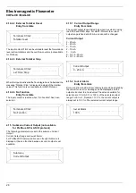
The low flow cutoff value can be set between 0 and 10.0 % of
the flow range end value. Between zero flow and the low flow
cutoff limit the flow is not integrated. The current output is set to
its zero value.
A 1 % hysteresis is incorporated in the low flow cutoff limit.
4.8
Damping
Numeric entries
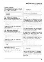
The damping can be set in the range from 0.5 to 99.9999 s.The
entry refers to the response time for the output to reach 99 % of
its final value for a step change in the flowrate. It is effective for
the indicated values in the display and the current output.
4.9
Filter (Noise Reduction)
Entry from table
A digital filter is included in the converter especially for pulsating
or noisy flow signals. It smooths the indications in the display
and the current output. When the filter is turned on the damping
value setting can be reduced. The converter response time is
not affected.
The “Filter” is mode is selected using the STEP or DATA keys
and turned on by pressing ENTER. The filter is active when a
damping time > 2.4 s is set. For HART-Protocol there is no
relationship between the Filter and the Damping settings.
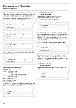
Noise Reduction Response
The output signal of the converter is shown with the filter OFF
and ON.
Fig. 14
Fig. 15
Low Flow Cutoff
1.000 %
Damping
10.0000 s
% Noise Signal
2 min
Filter OFF
Filter ON
Time
Fig. 16
Noise Reduction
Содержание COPA-XE
Страница 4: ......
Страница 24: ...18 Electromagnetic Flowmeter COPA XE MAG XE ...


