


8
Electromagnetic Flowmeter
COPA-XE / MAG-XE
3.
Programming the Converter
3.1
General Display Formats
After the power is turned on the Model Number of the converter
is displayed in the first line and the software version together
with its revision level in the second line. Then the process
information values are displayed.
The present flow direction is indicated in the first line of the
display (
→
F for forward or
←
R for reverse) together with the
instantaneous flow rate value in percent or direct reading
engineering units. In the second line the totalizer value for the
present flow direction is displayed to a max. of seven digits
followed by the units.
The totalizer value, in the appropriated units, always represents
the true value regardless of the pulse factor setting. This display
combination is referred to in the text by the term process
information.
The totalizer value for the opposite flow direction can be
displayed by pressing the STEP- or DATA key.
1st Line
Forward direction instantaneous flowrate
2nd Line
Forward direction totalizer value
1st Line
Forward direction instantaneous flowrate
2nd Line
Reverse totalizer value (multiplex operation)
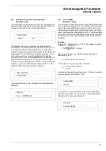
1st Line
Forward direction instantaneous flowrate
2nd Line
Totalizer overflow.
→
F and m3 blink.
A totalizer overflow occurs whenever the totalizer value
reaches 9,999,999 units. When the totalizer value in one flow
direction is greater than 9,999,999 units, the flow direction
symbol (
→
F or
←
R) and the units (e.g. m3) blink in the 2nd
line. A converter software counter can register a max. of 250
overflows. The overflow indication can be reset separately for
each flow direction by pressing ENTER.
If an error is detected an error message is displayed in the
1st line.
This message is displayed alternately in clear text and then by
its corresponding error code. The clear text message is only
displayed for the error with the highest priority while all other
detected errors are indicated by their error codes in the display.
In addition to the error message in the display an alarm signal
is transmitted over an optocoupler output and the current output
is set to 0 % or 130 % or 3.6 mA. The frequency output is
always set to 0 % (does not apply to Error Code 6).
→
F
98.14 l/s
→
F
12.30000m3
→
F
98.14 l/s
←
R
516.0000m3
→
F
70.01 l/s
→
F
10230
m3
Error
Code
Clear Text
Cause
0
1
2
3
4
5
6
7
8
9
A
B
C
Empty pipe
A/D saturated
U
ref
too small
Flowrate > 130 %
Zero return
RAM defective
Totalizer
U
refp
too large
U
refn
too large
Excitation frequency
Max. Alarm
Min. Alarm
Primary data
Pipeline not full.
A/D-Converter saturated.
Pos. or neg. reference too small.
Flowrate greater than 130 %.
Ext. zero return contact activated.
Data in RAM corrupted.
Totalizer value corrupted.
Positive reference too large
Negative reference too large
Supply power frequency or
Driver/Digital board defective.
Max. alarm value exceeded.
Value below min. alarm value
Error in external EEPROM or it
is not installed.
Error Codes by Priority
Flowrate >
130%
→
F
12.300
m3
Содержание COPA-XE
Страница 4: ......
Страница 24: ...18 Electromagnetic Flowmeter COPA XE MAG XE ...


