


98 Installation
WARNING!
As the inputs pictured above are not insulated according to
IEC 60664, the connection of the motor temperature sensor requires double or
reinforced insulation between motor live parts and the sensor. If the assembly
does not fulfil the requirement,
• the I/O board terminals must be protected against contact and must not be
connected to other equipment, or
• the temperature sensor must be isolated from the I/O terminals.
Start interlock (XDI:A)
Terminal XDI:A must be jumpered to XD24:3 to enable the drive start.
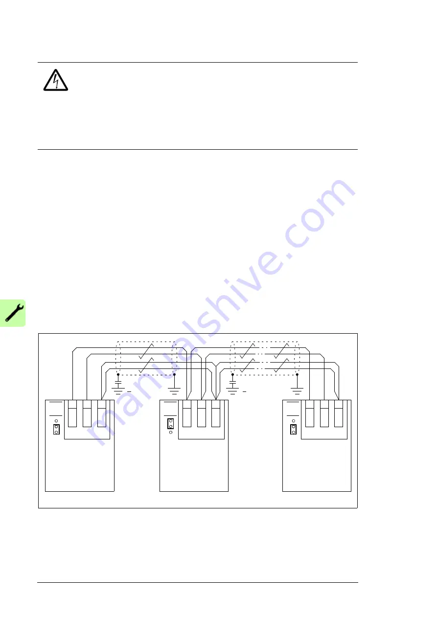
Drive-to-drive link (XD2D)
The drive-to-drive link is a daisy-chained RS-485 transmission line that allows basic
master/follower communication with one master drive and multiple followers.
Termination activation jumper T (see section
above) next to this terminal block
must be set to the ON position on the drives at the ends of the drive-to-drive link. On
intermediate drives, the jumper must be set to the OFF position.
Shielded twisted-pair cable (~100 ohm, for example PROFIBUS-compatible cable) must
be used for the wiring. For best immunity, high quality cable is recommended. The cable
should be kept as short as possible; the maximum length of the link is 100 meters (328 ft).
Unnecessary loops and running the cable near power cables (such as motor cables) must
be avoided. The cable shields must be grounded to the control cable clamp plate on the
drive as shown on page
.
The following diagram shows the wiring of the drive-to-drive link.
Safe torque off (XSTO)
For the drive to start, both connections (OUT1 to IN1, and OUT2 to IN2) must be closed.
By default, the terminal block has jumpers to close the circuit. Remove the jumpers before
connecting an external Safe torque off circuitry to the drive. See page
XD2D
...
1
T
J3
Termination
ON
JCU
Drive 1
B
2
A
3
BG
N
D
XD2D
1
J3
Termination
OFF
JCU
Drive 2
B
2
A
3
BG
N
D
T
XD2D
1
T
J3
Termination
ON
JCU
Drive n
B
2
A
3
BG
N
D
3.3 nF
> 630 V AC
3.3 nF
> 630 V AC
Содержание ACQ810-04
Страница 1: ...ABB industry specific drives Hardware manual ACQ810 04 drive modules 200 to 500 kW 300 to 700 hp ...
Страница 4: ......
Страница 10: ...10 ...
Страница 22: ...22 Introduction to the manual ...
Страница 42: ...42 Planning the cabinet installation ...
Страница 75: ...Installation 75 Assembly drawing frame G1 ...
Страница 76: ...76 Installation Assembly drawing frame G2 ...
Страница 83: ...Installation 83 3 6a 6b 5 4 8 4 8 6a 6b 7a 7b 7b ...
Страница 84: ...84 Installation Assembly drawing of installing the drive module to the cabinet frame G1 ...
Страница 85: ...Installation 85 Assembly drawing of installing the drive module to the cabinet frame G2 ...
Страница 89: ...Installation 89 3AUA0000038989 TXD transmitter RXD receiver JRIB V2 V1 V7 V6 1 2 APOW 2 JINT 3 JRIB 1 4 4 JGDR ...
Страница 100: ...100 Installation ...
Страница 104: ...104 Installation checklist ...
Страница 106: ...106 Start up ...
Страница 108: ...108 Fault tracing ...
Страница 128: ...128 Technical data ...
Страница 130: ...130 Dimension drawings Frame G1 Drive module dimensions ...
Страница 131: ...Dimension drawings 131 Frame G1 Drive module dimensions with optional cabling panels H381 ...
Страница 132: ...132 Dimension drawings ...
Страница 133: ...Dimension drawings 133 Frame G1 Cabling panels H381 installed into a Rittal TS 8 cabinet ...
Страница 134: ...134 Dimension drawings Frame G2 Drive module dimensions ...
Страница 135: ...Dimension drawings 135 Frame G2 Drive module dimensions with optional cabling panels H381 ...
Страница 136: ...136 Dimension drawings ...
Страница 137: ...Dimension drawings 137 Frame G2 Cabling panels H381 installed into a Rittal TS 8 cabinet ...
Страница 138: ...138 Dimension drawings Bottom plate ...
Страница 142: ...142 du dt filters ...
Страница 144: ...3AUA0000120538 Rev A EN 2012 06 27 Contact us www abb com drives www abb com drivespartners ...