


Section 2 Installation
Installing the Mains Breaker Unit
3BSE 027 941 R301
79
Installing the Mains Breaker Unit
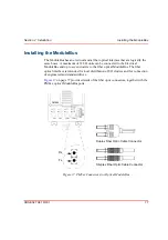
The mains breaker unit is supplied in separate components that must be mounted
onto a DIN-rail in order to form a complete assembly. Different distribution options
are available, but for the sake of simplicity, the installation described covers the
redundant power supplies/independent power supplies option. See
Use the following procedure to correctly install the mains breaker unit:
1.
Mount the mains breaker unit components onto the DIN-rail, from left to right,
close to the incoming power supply, in the order given below (see
a.
A DIN-rail end-stop (1).
b.
The terminal for the incoming protective ground (2).
c.
The two terminals for the incoming Live and Neutral mains power (3).
These terminals are equipped with built-in jumpers which, if necessary,
can be opened to provide complete mains input power isolation.
d.
The miniature mains breaker unit (4).
e.
The protective ground distribution terminal (5).
f.
The mains distribution terminal block (6), depending on the required
configuration.
g.
A DIN-rail end-stop (1).
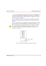
2.
Connect the incoming mains, the protective ground terminals, the mains
breaker and the distribution terminals as shown in
3.
Install the two required links (7), fuse holders (8) and jumpers (9) onto
the distribution terminals. Fit the required fuses into the fuse holders, (glass
tube type, 5 x 20 mm (0.2 x 0.8 in)).
The protective ground terminal (2) is fitted with a knife-like device to provide
automatic grounding to the DIN-rail.
Содержание AC 800M
Страница 1: ...ControlIT AC 800M Version 2 1 Controller Hardware Hardware and Operation...
Страница 2: ......
Страница 3: ...Controller Hardware Hardware and Operation ControlIT AC 800M Version 2 1...
Страница 10: ...7DEOH RI RQWHQWV 10 3BSE 027 941 R301...
Страница 20: ...Related Documentation About This Book 20 3BSE 027 941 R301...
Страница 26: ...Operating Environment Safety Summary 26 3BSE 027 941 R301...
Страница 42: ...Product Release History Section 1 Introduction 42 3BSE 027 941 R301...
Страница 108: ...Powering from an External 24 V DC Source Section 3 Configuration 108 3BSE 027 941 R301...
Страница 118: ...Verification of Redundant CPU Section 4 Operation 118 3BSE 027 941 R301...
Страница 212: ...Low Voltage Directive LVD Appendix D Directive Considerations 212 3BSE 027 941 R301...
Страница 214: ...Hazardous Location Approval Appendix E Standards 214 3BSE 027 941 R301...
Страница 228: ...QGH 228 3BSE 027 941 R301...
Страница 229: ......


