


CI851 and TP851 – PROFIBUS DP Interface
Appendix A Hardware Units
154
3BSE 027 941 R301
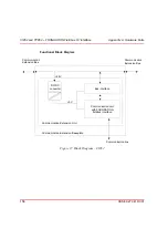
Functional Block Diagram
Figure 36. Block Diagram – CI851
Bus interface
Communication unit
AnyBus -M PROFIBUS-DP
+5 V
+24 V
Communication Extension Unit
Communication Extension Baseplate
Communication line
Communication
Extension Bus
Communication
Extension Bus
DC/DC
converter
Содержание AC 800M
Страница 1: ...ControlIT AC 800M Version 2 1 Controller Hardware Hardware and Operation...
Страница 2: ......
Страница 3: ...Controller Hardware Hardware and Operation ControlIT AC 800M Version 2 1...
Страница 10: ...7DEOH RI RQWHQWV 10 3BSE 027 941 R301...
Страница 20: ...Related Documentation About This Book 20 3BSE 027 941 R301...
Страница 26: ...Operating Environment Safety Summary 26 3BSE 027 941 R301...
Страница 42: ...Product Release History Section 1 Introduction 42 3BSE 027 941 R301...
Страница 108: ...Powering from an External 24 V DC Source Section 3 Configuration 108 3BSE 027 941 R301...
Страница 118: ...Verification of Redundant CPU Section 4 Operation 118 3BSE 027 941 R301...
Страница 212: ...Low Voltage Directive LVD Appendix D Directive Considerations 212 3BSE 027 941 R301...
Страница 214: ...Hazardous Location Approval Appendix E Standards 214 3BSE 027 941 R301...
Страница 228: ...QGH 228 3BSE 027 941 R301...
Страница 229: ......


