


Section 4 Operation
Verification of Redundant CPU
3BSE 027 941 R301
117
Verification of Redundant CPU
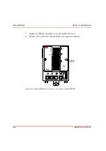
Check, in redundant configuration, the following LED indicators on PM861/PM864
(see
To check that the redundancy, i.e. the backup CPU, is working correctly, perform a
manual switch-over from the Primary CPU to the Backup CPU. A manual switch-
over is initiated by:
•
resetting the Primary CPU.
•
powering off the Primary CPU.
Check that the yellow DUAL LED subsequently lights up on both CPUs, and that
the PRIM LED lights up on the former Backup CPU now acting as Primary CPU.
For other units see
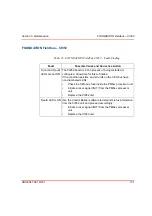
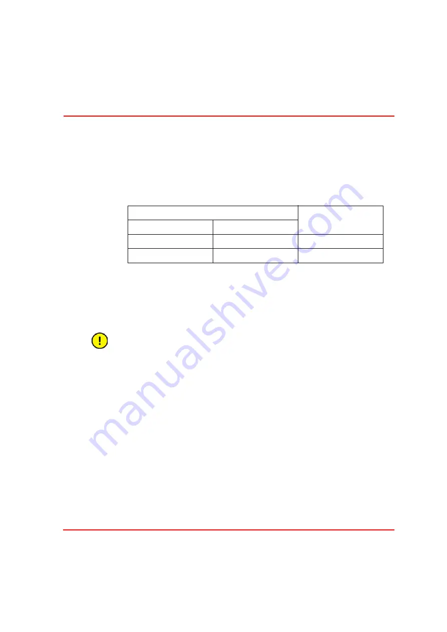
Table 19. AC 800M Controller (PM861/PM864) – Verification of Satisfactory
System Operation in Redundant configuration
LED Indicator Status
AC 800M Controller
Status
Primary CPU
Back-up CPU
PRIM(ary) yellow ON
PRIM(ary) yellow OFF
OK
DUAL yellow ON
DUAL yellow ON
OK
The RCU Link Cable must NEVER be removed from the primary Processor
Unit during operation. Removal of the cable may cause the unit to stop.
Содержание AC 800M
Страница 1: ...ControlIT AC 800M Version 2 1 Controller Hardware Hardware and Operation...
Страница 2: ......
Страница 3: ...Controller Hardware Hardware and Operation ControlIT AC 800M Version 2 1...
Страница 10: ...7DEOH RI RQWHQWV 10 3BSE 027 941 R301...
Страница 20: ...Related Documentation About This Book 20 3BSE 027 941 R301...
Страница 26: ...Operating Environment Safety Summary 26 3BSE 027 941 R301...
Страница 42: ...Product Release History Section 1 Introduction 42 3BSE 027 941 R301...
Страница 108: ...Powering from an External 24 V DC Source Section 3 Configuration 108 3BSE 027 941 R301...
Страница 118: ...Verification of Redundant CPU Section 4 Operation 118 3BSE 027 941 R301...
Страница 212: ...Low Voltage Directive LVD Appendix D Directive Considerations 212 3BSE 027 941 R301...
Страница 214: ...Hazardous Location Approval Appendix E Standards 214 3BSE 027 941 R301...
Страница 228: ...QGH 228 3BSE 027 941 R301...
Страница 229: ......


