


Appendix A Hardware Units
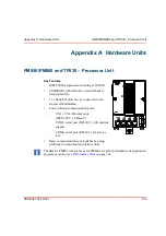
CI851 and TP851 – PROFIBUS DP Interface
3BSE 027 941 R301
153
CI851 and TP851 – PROFIBUS DP Interface
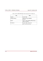
Key Features
•
Provides one PROFIBUS DP port, (a DB9 female
connector located on the TP851 Baseplate).
•
Simple DIN-rail mounting
•
The CI851 handles cyclic read and write messages
to the slaves on the PROFIBUS DP. The minimum
cycle time can be 1 ms, however, but this will
depend on the baud rate used and the number of
attached slaves.
•
By using repeaters it is possible to connect a
maximum of 124 nodes to one PROFIBUS DP (32
nodes are permitted on one segment).
•
Pre-set, two-letter Alpha code locking device
installed in unit base prevents mounting of
incompatible components.
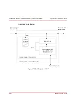
Description
The CI851 / TP851 is used for connecting to remote I/O.
Via an external gateway on PROFIBUS DP, field
instruments (on PROFIBUS DP) can be connected to AC
800M. The TP851 Baseplate has one female DB9
connector for connecting PROFIBUS DP. The baseplate
has a code lock, see
on page 54, that prevents the
installation of an incorrect type of unit onto the TP851
Baseplate.
The CI851 expansion unit contains the CEX-bus logic, a communication unit and a
DC/DC converter that supplies appropriate voltages from the +24V supply, via the
CEX-bus. The PROFIBUS DP must always be terminated at the two outer nodes.
ABB recommends the use of connectors with built-in termination since the fieldbus
will always be terminated even if fully disconnected from the unit.
F
R
Rx/Tx
RTS
CI851
Содержание AC 800M
Страница 1: ...ControlIT AC 800M Version 2 1 Controller Hardware Hardware and Operation...
Страница 2: ......
Страница 3: ...Controller Hardware Hardware and Operation ControlIT AC 800M Version 2 1...
Страница 10: ...7DEOH RI RQWHQWV 10 3BSE 027 941 R301...
Страница 20: ...Related Documentation About This Book 20 3BSE 027 941 R301...
Страница 26: ...Operating Environment Safety Summary 26 3BSE 027 941 R301...
Страница 42: ...Product Release History Section 1 Introduction 42 3BSE 027 941 R301...
Страница 108: ...Powering from an External 24 V DC Source Section 3 Configuration 108 3BSE 027 941 R301...
Страница 118: ...Verification of Redundant CPU Section 4 Operation 118 3BSE 027 941 R301...
Страница 212: ...Low Voltage Directive LVD Appendix D Directive Considerations 212 3BSE 027 941 R301...
Страница 214: ...Hazardous Location Approval Appendix E Standards 214 3BSE 027 941 R301...
Страница 228: ...QGH 228 3BSE 027 941 R301...
Страница 229: ......


