


Section 2 Installation
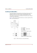
Installing the PROFIBUS DP-V1 Interface, CI854/TP854
3BSE 027 941 R301
73
Installation of PROFIBUS DP-V1
For installation of the fieldbus and recommended certified fieldbus devices and
components, see
on page 17 and
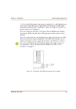
. The PROFIBUS DP-V1 must be connected with
shielded twisted pair cables.
Table 13. CI854 – PROFIBUS DP-V1 Connector
PIN
Designation
Description
1
Shield
Shield/protective ground
2
–
Not Used
3
RxD/TxD-P
Receive/Transmit Data P-line
4
CNTR-P
Indicates Direction to Repeater (TTL)
5
DGND
Digital Ground
6
VP
+5 V, for terminating resistors
7
–
–
8
RxD/TxD-N
Receive/Transmit Data
N-line
9
DGND
Digital Ground
Additional information on PROFIBUS DP-V1 and other suitable components is
available, on the Internet, at the PROFIBUS User Organization web site.
Содержание AC 800M
Страница 1: ...ControlIT AC 800M Version 2 1 Controller Hardware Hardware and Operation...
Страница 2: ......
Страница 3: ...Controller Hardware Hardware and Operation ControlIT AC 800M Version 2 1...
Страница 10: ...7DEOH RI RQWHQWV 10 3BSE 027 941 R301...
Страница 20: ...Related Documentation About This Book 20 3BSE 027 941 R301...
Страница 26: ...Operating Environment Safety Summary 26 3BSE 027 941 R301...
Страница 42: ...Product Release History Section 1 Introduction 42 3BSE 027 941 R301...
Страница 108: ...Powering from an External 24 V DC Source Section 3 Configuration 108 3BSE 027 941 R301...
Страница 118: ...Verification of Redundant CPU Section 4 Operation 118 3BSE 027 941 R301...
Страница 212: ...Low Voltage Directive LVD Appendix D Directive Considerations 212 3BSE 027 941 R301...
Страница 214: ...Hazardous Location Approval Appendix E Standards 214 3BSE 027 941 R301...
Страница 228: ...QGH 228 3BSE 027 941 R301...
Страница 229: ......


