


Publication No. PPC11A-HRM/1
Control and Status Registers 79
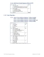
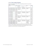
5.15.2 Timer 0 Control/Status Register 2 (Offset 0x651),
Timer 1 Control/Status Register 2 (Offset 0x659),
Timer 2 Control/Status Register 2 (Offset 0x661) and
Timer 3 Control/Status Register 2 (Offset 0x669)
Setting bit 4 in
any
Timer Control and Status Register 2 has the same effect of
latching
all
timers on a read of the Timer 0 LS Byte.
Bits
Description
Default
7 to 5
Reserved
000
b
4
Timer read latch select:
1 = Latch all timers on read of Timer 0 LS Byte
0 = Latch individual timers on the read of individual Timer LS Byte
3 & 2
Reserved
00
b
1
Timer One-shot Enable:
1=Timer will count down and stop
0=Timer will count down and reload at terminal count
0
Timer Enable:
1=Timer enabled
0 = Timer disabled
5.15.3 Timer 0 Interrupt Clear Register (Offset 0x652),
Timer 1 Interrupt Clear Register (Offset 0x65A),
Timer 2 Interrupt Clear Register (Offset 0x662) and
Timer 3 Interrupt Clear Register (Offset 0x66A)
Any write to this register clears the corresponding timer IRQ.
Содержание PPC11A
Страница 1: ...Hardware Reference Manual PPC11A 6U VME Single Board Computer Edition 1 Publication No PPC11A HRM 1 ...
Страница 27: ...Publication No PPC11A HRM 1 Functional Description 27 Figure 4 2 Block Diagram T2081 ...
Страница 113: ...Publication No PPC11A HRM 1 Connectors 113 Figure 6 2 Rear Connector Position ...


