


74 PPC11A 6U VME Single Board Computer
Publication No. PPC11A-HRM/1
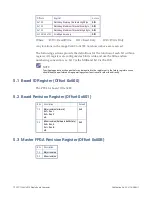
5.7
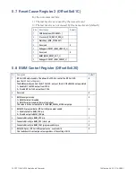
Reset Cause Register 2 (Offset 0x61C)
For the non-reserved bits:
1 = The last reset was caused by the named event
0 = The last reset was not caused by the named event (default)
Bits Reset Cause
Default
7
VME backplane (SYSRESET~)
6
Processor (CPU_RESET_REQ_L)
5
Watchdog (AWD_SYSRESET)
4
Reserved
0
3
Debugger HRESET (BDM_HRESET_L)
2
Reserved
0
1
BMM (BMM_RESET_OUT_L)
0
Debugger SRESET (BDM_SRESET_L)
5.8
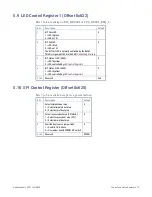
BMM Control Register (Offset 0x620)
Bit Description
Default
7
BIT Fail LED output enable. This allows the FPGA to control the BIT Fail LED
(see the
The BMM normally controls the BIT Fail LED - only set this bit if the BMM is not populated.
1 = Enable BIT Fail LED output from FPGA
0 = Disable BIT Fail LED output from FPGA
0
6
Reserved
0
5
BMM serial port mode:
1 = BMM Serial port disabled
0 = BMM Serial port enabled (normal operation)
This value is driven out unaltered to the BMM_SERIAL_MODE output pin
0
4
BMM_PGD (program data = BIT Fail LED) pin output enable:
1 = Enable output to BMM_PGD pin
0 = Disable output to BMM_PGD pin
0
3
Connected directly to BMM_VPP pin
1
2
Connected directly to BMM_PGC (clock) pin
1
1
Connected directly to BMM_PGM (program enable) pin
0
0
BMM_PGD pin (= BIT Fail LED) output value - see also bit 4.
This reads back the actual pin value regardless of the setting of bit 4
0
Содержание PPC11A
Страница 1: ...Hardware Reference Manual PPC11A 6U VME Single Board Computer Edition 1 Publication No PPC11A HRM 1 ...
Страница 27: ...Publication No PPC11A HRM 1 Functional Description 27 Figure 4 2 Block Diagram T2081 ...
Страница 113: ...Publication No PPC11A HRM 1 Connectors 113 Figure 6 2 Rear Connector Position ...


