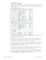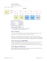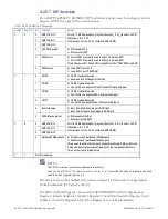
56 PPC11A 6U VME Single Board Computer
Publication No. PPC11A-HRM/1
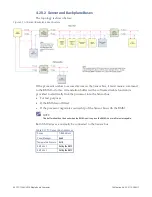
4.20.2 Sensor and Backplane Buses
The topology is shown below:
Figure 4-7 I
2
C Sensor/Backplane Bus Structure
If the processor wishes to access devices on the Sensor bus, it must issue a command
to the BMM to do this. A translation buffer (with a software disable function) is
provided to electrically link the processor into the Sensor bus:
•
For test purposes
•
If the BMM is not fitted
•
If the processor negotiates ownership of the Sensor bus with the BMM
NOTE
This buffer should not be used when the BMM is active, since the BMM is not multi-master capable.
Both XMC sites are normally be connected to the Sensor bus.
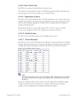
Table 4-27 I
2
C Sensor Bus Addresses
Device
7-Bit Address
Power Manager
0x60
Temperature Sensors
0x18
XMC site 1
Set by the XMC
XMC site 2
Set by the XMC
Содержание PPC11A
Страница 1: ...Hardware Reference Manual PPC11A 6U VME Single Board Computer Edition 1 Publication No PPC11A HRM 1 ...
Страница 27: ...Publication No PPC11A HRM 1 Functional Description 27 Figure 4 2 Block Diagram T2081 ...
Страница 113: ...Publication No PPC11A HRM 1 Connectors 113 Figure 6 2 Rear Connector Position ...

