5-2
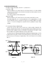
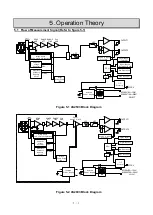
The signal fed from the bridge box or a transducer is applied to the INPUT connector
1
of this
product and amplified through High impedance and low zero-drift preamplifier.
To this preamplifier are added the outputs of a 4-digit digital calibration voltage generating circuit
(CAL), a resistance unbalance adjusting circuit (R BAL) and a capacitance unbalance auto
eliminating circuit (C BAL), only the signal of which is fed to the subsequent stage.
The signal which has been amplified through a main amplifier, and then outputted via a
LPF(Low-pass Filter) and HPF(High-pass Filter) at AS2503.
The signal which has been amplified through a main amplifier, and then outputted via a signal
isolation circuit and LPF and HPF at AS2603.
There are two output systems: the output of OUTPUT 1
3
is displayed on a level meter
②
, while
the output of OUTPUT 2
4
is displayed on a digital monitor
③
.
Содержание AS2503
Страница 1: ...AS2503 AS2603 DC BRIDGE SYSTEM DYNAMIC STRAIN AMPLIFIERS INSTRUCTION MANUAL 1WMPD4003356 ...
Страница 2: ......
Страница 4: ......
Страница 30: ......
Страница 46: ......
Страница 68: ......
Страница 83: ...9 5 9 3 External Dimensions 9 3 1 Amplifier Unit AS2503 ...
Страница 84: ...9 6 9 3 2 Amplifier Unit AS2603 ...
Страница 85: ...9 7 9 3 3 Panel Cut Sizes ...
Страница 87: ...9 9 9 3 5 Rack mount Case Rack Rail Elongate Hole ...
Страница 88: ...9 10 9 3 6 Bridge Box 5370 and 5373 ...

