2-9
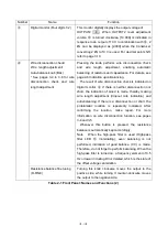
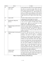
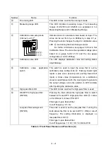
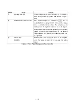
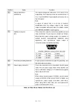
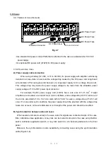
2.5 Rear Panel: Names and Functions (See Table 2-2)
Number
Name
Function
1
Input connector (INPUT)
The bridge box or connector or a transducer is
connected. The connector should be an input connector
for strain measurement confirming the standards of The
Japanese Society for Non-Destructive Inspection
(NDIS4102).
2
Bridge power voltage selection
switch
(BV)
Selection of power voltage applied to the bridge can be
switched (0.5 V or 20 V).
3
Output connector 1
(OUTPUT1)
The output voltage and current are
10 V and
5 mA,
respectively. This connector can be connected to a
recorder (e.g. thermal-dot recorder or data acquisition
devices) or A/D converter, which accept voltage signals
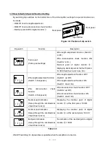
Table 2-2 Rear Panel: Names and Functions
(1)
表2-1 前面パネル(名称と機能)
①
-f
②
③
④
⑤
⑥
⑦
⑧
⑨
⑩
⑪
⑫
⑬
⑭
⑯
⑮
⑱
1
2
3
5
7
4
6
⑲
⑰
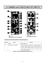
Figure 2-1 Front view of
AS amplifier unit (AS2603)
Figure 2-2 Rear view of
AS amplifier unit
Содержание AS2503
Страница 1: ...AS2503 AS2603 DC BRIDGE SYSTEM DYNAMIC STRAIN AMPLIFIERS INSTRUCTION MANUAL 1WMPD4003356 ...
Страница 2: ......
Страница 4: ......
Страница 30: ......
Страница 46: ......
Страница 68: ......
Страница 83: ...9 5 9 3 External Dimensions 9 3 1 Amplifier Unit AS2503 ...
Страница 84: ...9 6 9 3 2 Amplifier Unit AS2603 ...
Страница 85: ...9 7 9 3 3 Panel Cut Sizes ...
Страница 87: ...9 9 9 3 5 Rack mount Case Rack Rail Elongate Hole ...
Страница 88: ...9 10 9 3 6 Bridge Box 5370 and 5373 ...

