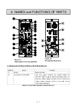
2-5
Number
Name
Function
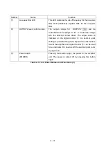
⑰
Low-pass filter LED
This LED indicates the cut-off frequency for the low-pass
filter. W/B (wideband) signifies OFF for the low-pass
filter.
⑱
OUTPUT2 level control volume
The output voltage for OUTPUT2 4 can be
controlled from the rating 10 V to 1 V. Control the voltage
with the attached screw driver. The output value is
indicated on the digital monitor
③
. As decimal point
shifting is possible through the dip switch on the bottom
face of the amplifier unit, digital monitor
③
can be used
for an indicator. For how to shift the decimal point, refer
to page 3-10.
⑲
Power switch
(POWER)
Pressing this switch supply the power to the amplifier
unit. The power is turned off by pressing this button
again.
Table 2-1 Front Panel: Names and Functions (5)
Содержание AS2503
Страница 1: ...AS2503 AS2603 DC BRIDGE SYSTEM DYNAMIC STRAIN AMPLIFIERS INSTRUCTION MANUAL 1WMPD4003356 ...
Страница 2: ......
Страница 4: ......
Страница 30: ......
Страница 46: ......
Страница 68: ......
Страница 83: ...9 5 9 3 External Dimensions 9 3 1 Amplifier Unit AS2503 ...
Страница 84: ...9 6 9 3 2 Amplifier Unit AS2603 ...
Страница 85: ...9 7 9 3 3 Panel Cut Sizes ...
Страница 87: ...9 9 9 3 5 Rack mount Case Rack Rail Elongate Hole ...
Страница 88: ...9 10 9 3 6 Bridge Box 5370 and 5373 ...

