4-3
4.2 Input Connection
4.2.1 Examples of Strain Gauge Bridge Configurations
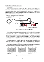
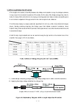
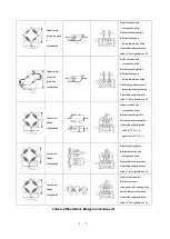
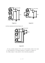
When incorporating one or more strain gauges into the four arms of a bridge, a quarter-, half-
or full-bridge configuration can be used. These configurations can further be classified into same
sign equivalent values, different sign equivalent values, and different sign constant proportional
values according to the type of strain applied to the strain gauge(s). In addition, by effectively
utilizing the characteristics of the bridge, measures can be taken to compensate for the effect of
temperatures, eliminate errors, or increase the output.
This section describes examples of bridge configurations that are generally used. The following
symbols are used:
R: Resistance of fixed register (
)
Rg: Resistance value of strain gauge (
)
Rd: Resistance value of dummy gauge (
)
r: Resistance value of lead wire (
)
e: Output voltage from bridge (V)
K: Gauge factor of strain gauge to be used (2.00)
: Amount of strain applied (
m/m)
E: Bridge excitation voltage (V)
: Poisson’s rate of an object to be measured
For information on how to cement strain gauges and on the characteristics of strain gauges,
refer to the technical manuals provided by the strain gauge
manufacturers, or “Strain
Measurement I” or “Strain Measurement II” published by the Japanese Society of
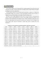
Non-destructive Inspection. The wiring methods of the bridge boxes shown in Table 4 are applied
where bridge box 5370 is used.
Содержание AS2503
Страница 1: ...AS2503 AS2603 DC BRIDGE SYSTEM DYNAMIC STRAIN AMPLIFIERS INSTRUCTION MANUAL 1WMPD4003356 ...
Страница 2: ......
Страница 4: ......
Страница 30: ......
Страница 46: ......
Страница 68: ......
Страница 83: ...9 5 9 3 External Dimensions 9 3 1 Amplifier Unit AS2503 ...
Страница 84: ...9 6 9 3 2 Amplifier Unit AS2603 ...
Страница 85: ...9 7 9 3 3 Panel Cut Sizes ...
Страница 87: ...9 9 9 3 5 Rack mount Case Rack Rail Elongate Hole ...
Страница 88: ...9 10 9 3 6 Bridge Box 5370 and 5373 ...


