19
9.7
ANTIFREEZE
PROTECTION
RESISTANCES
(IF
THE
KA
ACCESSORY
IS
PRESENT)
The
antifreeze
resistances,
installed
on
the
outer
surfaces
of
the
evaporator
plates,
activates
even
when
the
unit
is
switched
off
(but
energized)
if
the
outlet
water
temperature
goes
below
4°C.
The
same
resistances
are
switched
off
when
the
temperature
measured
by
the
outlet
water
sensor
exceeds
6°C.
The
heating
cable
placed
on
the
basement
of
the
appliance
turns
on
when
the
outdoor
air
temperature
decreases
below
4°C
or
when
the
unit
starts
the
defrosting
cycle.
It
will
be
disactivated
if
the
outdoor
temperature
exceeds
6°C.
9.8
ON/OFF
REMOTE
CONTROL
AND
SUMMER/WINTER
MODES
The
terminal
block
has
two
digital
inputs
to
control
the
unit
via
an
external
consent.
SW
‐
SW:
Summer/winter
switching
mode
input
via
remote
control.
To
enable
this
feature,
set
the
parameter
H76=1
.
The
parameter
is
protected
by
maintainer
password
(could
be
changed
by
the
installer).
onoff
‐
onoff:
Remote
on
‐
off
input.
The
feature
is
already
enabled
by
default.
Remove
the
bridge
connection
in
the
terminal
block
to
put
the
unit
in
stand
‐
by
mode
(in
such
a
state
the
code
''
E00
''
will
appear
on
the
display
of
the
unit).
If
the
sanitary
operating
mode
is
activated,
the
on
‐
off
remote
function
will
switch
off
the
machine
provided
the
sanitary
set
had
not
yet
been
reached
(in
such
a
state
the
word
''
SAN
''
will
appear
on
the
display
of
the
appliance).
9.9
SANITARY
VALVE
ADJUSTMENT
To
activate
the
hot
sanitary
water
function,
be
sure
to
install
a
temperature
sensor
inside
the
tank
and
to
connect
it
to
the
SAN
‐
SAN
terminals.
Once
the
temperature
sensor
is
installed
and
connected,
it
is
necessary
to
set
the
parameter
H10
=
1
,
and
to
set
the
parameter
H20
=
6
.
To
set
these
parameters,
please
enter
the
maintainer
password
and
then
enter
the
PRG
‐
>Pss
‐
>PAr
‐
>Cnf
‐
>H10/H20
parameters
(the
configuration
could
be
done
by
the
installer).
If
the
hot
sanitary
water
temperature
is
below
the
set
point
value
(setted
at
48°C
by
default
and
adjustable
by
entering
the
PRG
‐
>
Set
‐
>SAN
menu),
the
unit
activates
the
sanitary
valve
and
the
frequency
of
the
compressor
will
be
reduced
to
the
minimum
value
for
2
minutes,
in
such
a
way
that
the
valve
can
divert
the
water
flow
towards
the
sanitary
tank.
After
the
water
flow
is
diverted,
the
compressor
changes
the
frequency
to
the
maximum
value
till
the
temperature
reaches
the
set
point
of
sanitary
water.
Once
reached
the
set
point
value,
the
valve
switches
to
the
stand
‐
by
mode
and
the
compressor
works
normally.
When
using
a
3
‐
way
valve
to
switch
‐
over
with
3
contacts
for
power
supply,
it
must
be
connected
to
the
terminals
NO1,
N,
NC1.
Otherwise,
in
the
case
of
using
a
3
‐
way
valve
for
switching
‐
over
with
2
contacts
for
power
supply
(with
spring
return),
it
must
be
connected
to
the
terminals
NO1
and
N.
Closed
contact
NO1
means
that
the
valve
is
energized
and
diverts
the
water
flow
to
the
sanitary
water
tank.
Open
contact
NO1
means
that
the
valve
is
de
‐
energized
and
diverts
the
water
flow
to
users.
While
shifting
from
domestic
water
to
sanitary
water,
the
operating
sensor
changes
from
“outlet
water
sensor”
to
“sanitary
tank
sensor”.
While
shifting
from
the
winter
operating
mode
to
the
sanitary
operating
mode,
the
compressor
does
not
switch
off,
and
reaches
the
highest
frequency;
on
the
other
hand,
while
shifting
from
the
summer
operating
mode
to
the
sanitary
operating
mode,
the
compressor
is
switched
off
to
wait
for
the
safety
timing.
9.10
ACTIVATION
OF
SANITARY
HOT
WATER
PRODUCTION
BY
DIGITAL
INPUT
Differently
to
the
use
of
the
temperature
probe,
the
activation
of
the
sanitary
hot
water
function
may
be
by
closing
the
digital
input
(SAN
SAN
terminals)
of
the
minichiller.
This
function
is
recommended
in
the
case
of
use
of
two
or
more
minichillers
in
cascade
linked
trougth
a
hydronic
connection
to
the
same
accumulation
tank
of
sanitary
hot
water;
in
this
way
the
activation
of
sanitary
hot
water
is
setted
through
the
probe
of
the
accumulation
tank
connected
to
the
first
minichiller,
while
the
other
minichillers
will
be
automatically
enabled
by
digital
consent.
Only
for
the
units
with
activation
of
sanitary
hot
water
production
by
digital
input
,
it
must
therefore
set
H20=0,
H45=28,
H54=128
.
For
each
minichiller
(except
the
last
one
of
the
cascade),
you
must
use
a
relay
(not
included),
controlled
by
the
output
230VAC
NO1
and
N
of
the
terminal
block,
that
can
enable
through
its
free
contacts
COM
and
NO
the
SAN
SAN
digital
input
of
the
following
minichiller
in
the
cascade.
Please
refer
to
the
wiring
diagram
below
for
such
configuration.
Содержание HPE Series
Страница 21: ......
Страница 29: ...28 ...
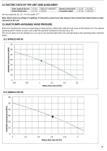
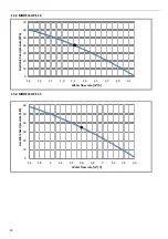
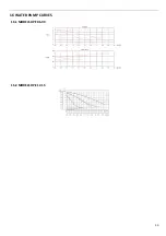
Страница 31: ...30 16 WATER PUMP CURVES 16 1 MODELS HPE 06 09 16 2 MODELS HPE 12 15 ...
Страница 34: ...33 19 3 HPE 12 15 IN OUT 1 M ...
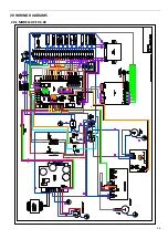
Страница 35: ...34 20 WIRING DIAGRAMS 20 1 MODELS HPE 06 09 ...
Страница 36: ...35 20 2 MODEL HPE 12 ...
Страница 37: ...36 20 3 MODEL HPE 15 ...
Страница 43: ...NOTE ...
Страница 44: ...NOTE ...
Страница 45: ...NOTE ...
Страница 46: ...NOTE ...
Страница 47: ......


