13
The
connections
indicated
below
are
standard.
Other
connections
are
shown
in
the
table
see
paragraph
9.17.
Terminal
Type
Connection
GND
Connect
the
grounding
wire
N1
Connect
the
power
supply
neutral
wire;
L1
Connect
thepower
supply
phase
wire;
(note
that,
in
the
three
‐
phases
versions
there
are
two
other
terminals,
L2
and
L3)
NC1
Digital
output
with
changeover
contact
Power
supply
NC
terminal
(230V
AC)
for
3
‐
way
valve
for
sanitary
hot
water
boiler
(used
only
for
3
‐
way
valve
with
3
contacts
for
power
supply
connection
to
switching
‐
over
to
the
plant
side)
(for
further
configuration
settings,
please
check
the
Paragraph
9.17)
N
Digital
output
with
changeover
contact
Power
supply
neutral
terminal
(230V
AC)
for
3
‐
way
valve
for
sanitary
hot
water
boiler
(for
further
configuration
settings,
please
refer
to
Paragraph
9.17)
NO1
Digital
output
with
changeover
contact
Power
supply
NO
terminal
(230V
AC)
for
3
‐
way
valve
for
sanitary
hot
water
boiler
(to
switch
‐
over
the
valve
to
the
boiller
side)
(for
further
configuration
settings,
please
refer
to
Paragraph
9.17)
NC2
Digital
output
with
changeover
contact
Power
supply
NC
terminal
(230V,
50Hz,
5A
resistive,
1
A
inductive)
for
3
‐
way
double
set
point
valve
for
radiant
panels.
(optional,
to
use
only
on
V2
series,
see
paragraph
21)
(for
further
configuration
settings,
please
refer
to
Paragraph
9.17)
N2
Digital
output
with
changeover
contact
Power
supply
neutral
terminal
(230V
AC)
for
3
‐
way
double
set
point
valve
for
radiant
panels
(optional,
to
use
only
on
V2
series,
see
paragraph
21.)
(for
further
configuration
settings,
please
refer
to
Paragraph
9.17)
NO2
Digital
output
with
changeover
contact
Power
supply
NO
terminal
(230V,
50Hz,
5A
resistives,
1
A
inductives)
3
‐
way
valve
double
set
point
for
radiant
panels
(optional,
to
use
only
on
V2
series,
see
paragraph
21.)
(for
further
configuration
settings,
please
refer
to
Paragraph
9.17)
R+
Modbus
+
signal
connection
to
remote
keyboard
R
‐
Modbus
‐
signal
connection
to
remote
keyboard
12V+
Power
output
for
remote
keyboard
(12V,
50Hz,
500mA)
12V
‐
Power
output
for
remote
keyboard
(12V,
50Hz,
500mA)
SE
Analog
(ST8)/digital
(DI7)
input
Humidistat
terminal
for
the
double
set
‐
point
regulation
(optional)
(for
further
configuration
settings,
please
refer
to
Paragraph
9.17)
SE
Analog
(ST8)/digital
(DI7)
input
Humidistat
terminal
for
the
double
set
‐
point
regulation
(optional)
(for
further
configuration
settings,
please
refer
to
Paragraph
9.17)
AEH
Digital
output
(DO3)
Sanitary
water
supplementary
heater
output
(230V,
50Hz,
5A)
(for
further
configuration
settings,
please
refer
to
Paragraph
9.17)
AEH
Digital
output
(DO3)
Sanitary
water
supplementary
heater
output
(230V,
50Hz,
5A)
(for
further
configuration
settings,
please
refer
to
Paragraph
9.17)
SAN
Analog
(ST9)/digital
(DI8)
input
Sanitary
water
boiler
sensor
terminal
(for
further
configuration
settings,
please
refer
to
Paragraph
9.17)
SAN
Analog
(ST9)/digital
(DI8)
input
Sanitary
water
boiler
sensor
terminal
(for
further
configuration
settings,
please
refer
to
Paragraph
9.17)
DO5
Digital
output
(DO5)
Output
for
double
set
point
valve
control
(230V,
50Hz,
5A
resistive,
1
A
inductive)
(optional
to
use
only
for
V2+
series,
see
Paragraph
22.)
DO5
Digital
output
(DO5)
Output
for
double
set
point
valve
control
(230V,
50Hz,
5A
resistive,
1
A
inductive)
(optional
to
use
only
for
V2+
series,
see
Paragraph
22.)
SW
Digital
input
Summer/winter
switching
mode
terminal
via
remote
control
(closed
=
summer/open
=
winter);
SW
Digital
input
Summer/winter
switching
mode
terminal
via
remote
control
(closed
=
Содержание HPE Series
Страница 21: ......
Страница 29: ...28 ...
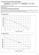
Страница 31: ...30 16 WATER PUMP CURVES 16 1 MODELS HPE 06 09 16 2 MODELS HPE 12 15 ...
Страница 34: ...33 19 3 HPE 12 15 IN OUT 1 M ...
Страница 35: ...34 20 WIRING DIAGRAMS 20 1 MODELS HPE 06 09 ...
Страница 36: ...35 20 2 MODEL HPE 12 ...
Страница 37: ...36 20 3 MODEL HPE 15 ...
Страница 43: ...NOTE ...
Страница 44: ...NOTE ...
Страница 45: ...NOTE ...
Страница 46: ...NOTE ...
Страница 47: ......


