37
21
CR
REMOTE
KEYBOARD
(OPTIONAL
ACCESSORY)
The
CRH
remote
keyboard
allows
you
to
set
the
operating
mode
of
THE
chiller
and
fan
coils
units
connected
to
a
RS485
network.
The
network
can
consist
of
up
to
5
cascaded
chillers
and
fan
coils
up
to
70
units
in
9
heating
zones.
The
keyboard
can
be
fitted
onto
the
E503
built
‐
in
wall
boxes.
Note:
For
more
informations,
please
see
the
manual
of
the
CRH
device
.
21.1
CONNECTION
OF
THE
CRH
KEYBOARD
TO
THE
MINICHILLER
The
connection
between
theCRH,
the
minichillers
and
terminal
units
is
very
simple
with
a
twisted
shielded
pair
cable
of
2x0.5m²
connected
in
series.
6:
to
be
connected
to
the
R
‐
exit
terminal
of
the
unit’s
exit
terminal
board;
7:
to
be
connected
to
the
R+
exit
terminal
of
the
unit’s
exit
terminal
board;
8:
to
be
connected
to
the
12V
‐
exit
terminal
of
the
unit’s
exit
terminal
board;
9:
to
be
connected
to
the
12V+
exit
terminal
of
the
unit’s
exit
terminal
board.
22
DOUBLE
SET
‐
POINT
KIT
(OPTIONAL
ACCESSORY)
22.1
PURPOSE
AND
SCOPE
The
function
of
double
set
‐
point
is
consisting
of
introducing
a
second
working
set
‐
point
of
the
plant
side
(in
both
cooling
and
heating
modes).
The
field
of
application
is
mainly
that
of
the
floor
cooling
assisted
by
fan
coil
for
dehumidification.
The
purpose
of
the
application
is
to
avoid
the
conditions
of
formation
of
condensation
in
the
floor,
and
to
ensure
thermo
hygrometric
the
welfare
at
any
case.
22.2
PARTS
AND
TECHNICAL
CHARACTERISTICS
OF
THE
KIT
Humidistat
•
Power
supply
12
‐
24
Vac
•
Internal
temperature
and
humidity
sensor
•
trimmer
for
setting
of
an
offset
from
‐
3°C
to
+3°C
respecting
the
dew
point
•
serial
RS485
DIN
rail
baseboard
•
applicable
on
DIN
rail
•
maximum
current
for
single
pole:
10A
ESC:
to
go
back
to
the
previous
menu
level
F1:
to
enter
the
menus
and
the
submenus
F2:
to
select
the
unit
and
to
set
the
parameter’s
value
ENTER:
to
enter
the
submenu
and
to
confirm
the
parameter’s
setting
DOWN:
to
decrease
the
parameter’s
value
or
to
scroll
the
menu
UP:
to
increase
the
parameter’s
value
or
to
scroll
the
menu
Содержание HPE Series
Страница 21: ......
Страница 29: ...28 ...
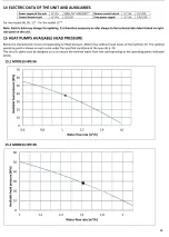
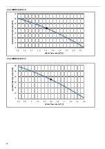
Страница 31: ...30 16 WATER PUMP CURVES 16 1 MODELS HPE 06 09 16 2 MODELS HPE 12 15 ...
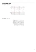
Страница 34: ...33 19 3 HPE 12 15 IN OUT 1 M ...
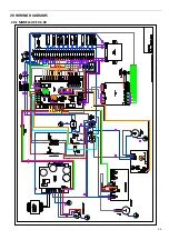
Страница 35: ...34 20 WIRING DIAGRAMS 20 1 MODELS HPE 06 09 ...
Страница 36: ...35 20 2 MODEL HPE 12 ...
Страница 37: ...36 20 3 MODEL HPE 15 ...
Страница 43: ...NOTE ...
Страница 44: ...NOTE ...
Страница 45: ...NOTE ...
Страница 46: ...NOTE ...
Страница 47: ......

