39
However,
it
is
recommended
to
use
an
external
relay,
included
in
the
double
set
‐
point
kit,
to
allow
the
connection
with
higher
loads
(up
to
8A
resistive,
1.6A
inductive)
and
at
the
same
time
separate
the
lines
of
the
power
supply
of
the
minichiller,
3
‐
way
valve
and
fan
coils
(in
this
case
it
is
necessary
to
provide
appropriate
protection
to
the
power
supply
line
of
the
fan
coil).
In
this
second
case,
the
relay
must
be
installed
on
board
machine
in
the
DIN
bar
of
the
user’s
terminal
block,
connecting
the
power
supply
for
V2
models
to
N2
‐
NC2
terminals,
or
to
DO5
‐
DO5
terminals
for
the
case
of
V2+
models
(the
output
of
DO5
‐
DO5
terminals
will
be
enabled
when
the
parameters
H60
and
H70
are
set
respectively
to
25
and
16
).
The
3
‐
way
valve
must
be
then
connected
to
the
outputs
of
the
relay
NO
COM
NC
if
it
has
3
contacts
for
power
supply,
otherwise
to
NO
‐
COM
terminals
if
it
has
2
contacts
for
power
supply
and
with
spring
return.
Please
refer
to
the
table
of
the
paragraph
9.17
for
the
configuration
of
the
paramters
The
3
‐
way
valve
that
can
be
energized
in
2
or
3
contacts
(not
included
within
the
kit)
The
3
‐
way
valve
is
applied
to
divert
the
water
flow
between
floor
plant
and
fan
coil
units.
In
the
case
of
a
3
‐
way
valve
with
2
contacts
for
power
supply
(with
return
spring),
when
the
3
‐
way
valve
is
not
activated,
the
outlet
of
the
valve
that
is
opened
must
be
connected
to
the
floor
plant.
In
the
case
of
a
3
‐
way
valve
with
3
contacts
for
power
supply,
the
way
of
the
valve
that
is
hydraulically
connected
to
the
floor
plant
must
be
activated
as
shown
in
the
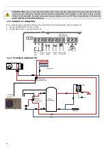
wiring
diagrams
presented
in
the
paragraph
22.8.
In
this
wiring
diagrams
show
the
direction
of
the
water
flow
to
divert
by
valve
to
either
floor
side
or
plant
side.
In
these
wiring
diagrams,
as
for
floor
side
or
plant
side,
it’s
intended
on
which
way
the
valve
will
be
diverted
when
it’s
activated.
22.6
ADJUASTABLE
SET
‐
POINT
Set
‐
point
type
Setpoint
(summer/winter)
Summer
Winter
First
set
‐
point
(°C)
Coo/Hea
7
(5÷18)
45
(35÷55)
Second
set
‐
point
(°C)
Co2/He2
18
(7÷23)
35
(25÷45)
Use
SET
button
on
the
control
panel
of
the
machine
to
adjust
the
setpoints.
The
second
set
‐
point
is
greater
than
the
first
set
‐
point
in
the
summer
and
lower
in
winter:
•
in
the
summer:
T2
≥
T
•
in
the
winter:
T2
≤
T
22.7
COMMUTATION
The
commutation
sequence
from
normal
set
‐
point
to
the
second
setpoint:
1) change
of
operating
set
‐
point
2a)
in
the
summer:
Commutation
of
the
3
‐
way
valve
only
when
the
second
set
‐
point
‐
5°C
is
reached.
2b)
in
the
winter:
commutation
of
the
3
‐
way
valve
only
when
the
second
set
‐
point
+5°C
is
reached.
(at
any
case
after
5
min
from
setpoints
modification,
the
commutation
of
the
valve
will
be
carried
out)
The
commutation
sequence
from
second
set
‐
point
to
the
normal
setpoint:
1) commutation
of
the
3
‐
way
valve
2) modification
of
the
operating
setpoint
after
a
lap
of
time
equal
to
the
required
time
for
opening
of
the
3
‐
way
valve.
(default
b04=30s
from
maintainer
menu)
Содержание HPE Series
Страница 21: ......
Страница 29: ...28 ...
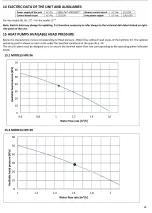
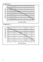
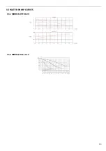
Страница 31: ...30 16 WATER PUMP CURVES 16 1 MODELS HPE 06 09 16 2 MODELS HPE 12 15 ...
Страница 34: ...33 19 3 HPE 12 15 IN OUT 1 M ...
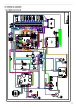
Страница 35: ...34 20 WIRING DIAGRAMS 20 1 MODELS HPE 06 09 ...
Страница 36: ...35 20 2 MODEL HPE 12 ...
Страница 37: ...36 20 3 MODEL HPE 15 ...
Страница 43: ...NOTE ...
Страница 44: ...NOTE ...
Страница 45: ...NOTE ...
Страница 46: ...NOTE ...
Страница 47: ......

