24
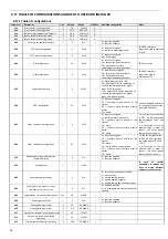
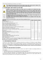
b14
Temperature
differential
in
heating
°C
10.0
‐
50.0÷80.0
I
b15
Set
‐
point
regulation
band
by
analog
input
0
‐
10V
/
5.0
0.0÷10.0
I
P03
Heat
pump
operation
mode
/
1
0÷1
I
0
=
continous
operation
1
=
thermoregulation
operation
P07
Maximum
speed
of
modulating
pump
%
Depending
on
the
model
0÷100
I
default÷100
(If
there
is
any
doubt
on
the
default
value,
please
contact
the
company)
Lower
values
than
those
of
default
compromise
the
optimal
operation
of
the
unit
P08
Minimum
speed
of
modulating
pump
%
Depending
on
the
model
0÷100
I
default÷100
(If
there
is
any
doubt
on
the
default
value,
please
contact
the
company)
Lower
values
than
those
of
default
compromise
the
optimal
operation
of
the
unit.
P16
Time
between
2
actuations
of
the
pump
in
periodical
mode
min
0
0÷600
I
P17
Operating
time
of
the
pump
in
periodical
mode
sec
0
0÷255
I
0
=
periodical
mode
is
disabled
r02
Set
point
of
anti
‐
freeze
heater
in
heating
mode
°C
4
3÷6
I
r03
Set
point
of
anti
‐
freeze
heater
in
cooling
mode
°C
4
3÷6
I
r06
Anti
‐
freeze
resistance
differential
°C
2,0
0,0÷25,5
I
r10
Enabling
the
auxiliary
heater
of
the
system
/
0
0÷1
I
0
=
functio
disabled
1
=
function
enabled
r11
Auxiliary
heater
differential
of
the
system
°C
0,0
0,0÷25,5
I
r12
Delay
on
activation
of
the
iauxiliary
heater
of
the
system
min
0
0÷255
I
r14
Exclusive
heaters
operation
/
0
0÷1
I
0
=
heaters
can
be
activated
simultaneously
1
=
heaters
can
be
activated
exclusively
r15
Enabling
of
auxiliary
heaters
of
sanitary
mode
/
0
0÷1
I
0
=
function
disabled
1
=
function
enabled
r16
Delay
on
activation
of
the
auxiliary
heaters
of
sanitary
mode
/
15
0÷255
I
r20
Priority
on
use
of
heaters
/
1
0÷1
I
0
=
priority
for
system
side
1
=
priority
for
sanitary
side
The
setting
of
this
parameter
is
required
only
if
r14
=
1.
r21
Enabling
the
mitigation
to
system
side
with
heaters
in
defrost
/
0
0÷1
I
0
=
function
disabled
1
=
function
enabled
r22
Set
for
the
joint
operation
of
auxiliary
heaters
‐
compressor
/
7
‐
127÷127
I
r23
Types
of
utilization
of
the
boiler
/
3
0÷3
I
0
=
Boiler
not
used
1
=
boiler
used
just
on
system
side;
2
=
boiler
used
just
for
sanitary
hot
water
side;
3
=
boiler
used
for
both
sanitary
hot
water
and
system
sides
r24
Types
of
utilization
of
the
auxiliary
heaters
/
3
0÷3
I
0
=
auxiliary
heaters
not
used
1
=
auxiliary
heaters
used
just
on
system
side
2
=
auxiliary
heaters
used
just
for
sanitary
hot
water
side
3
=
integrated
heaters
used
for
both
sanitary
hot
water
and
system
sides
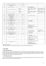
N.B.
U=user,
I=installer
All
configurations
could
not
be
selected
simultaneously.
For
more
information
please
contact
us.
9.18
ALARMS
9.18.1
Water
flow
switch
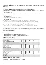
The
water
side
flow
switch
is
already
installed
inside
the
unit
and
DOES
NOT
HAVE
to
be
tampered
with
or
by
‐
passed
in
any
way.
The
flow
switch
is
by
‐
passed
for
10
seconds
after
the
unit’s
start
up.
The
alarm
will
automatically
reset
itself
for
the
first
time
and
it
will
be
reset
when
the
alarm
remains
off
for
at
least
5
seconds.
If
the
alarm
happens
more
than
one
time
per
hour,
it
cannot
automatically
reset
itself
and
so
you
should
manually
reset
it.
9.18.2
High
temperature
The
alarm
will
be
activated
when
the
outlet
water
temperature
sensor
becomes
higher
than
65°C
for
at
least
5
seconds.
It
turns
off
when
the
water
outlet
temperature
decreases
below
45°C.
Содержание HPE Series
Страница 21: ......
Страница 29: ...28 ...
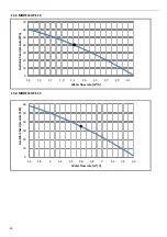
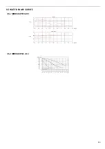
Страница 31: ...30 16 WATER PUMP CURVES 16 1 MODELS HPE 06 09 16 2 MODELS HPE 12 15 ...
Страница 34: ...33 19 3 HPE 12 15 IN OUT 1 M ...
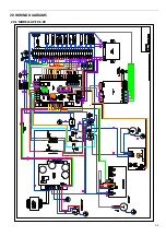
Страница 35: ...34 20 WIRING DIAGRAMS 20 1 MODELS HPE 06 09 ...
Страница 36: ...35 20 2 MODEL HPE 12 ...
Страница 37: ...36 20 3 MODEL HPE 15 ...
Страница 43: ...NOTE ...
Страница 44: ...NOTE ...
Страница 45: ...NOTE ...
Страница 46: ...NOTE ...
Страница 47: ......


