38
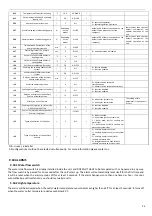
Relay
•
power
supply
230V
AC
•
max.
resistive
load
for
single
pole:
8A
•
max.
inductive
load
for
single
pole:
1,6A
22.3
FUNCTIONS
OF
HUMIDISTAT
By
reading
the
internal
sensor
of
temperature
and
humidity,
the
dew
point
will
be
calculated.
The
temperature
measured
from
the
internal
sensor
to
the
controller
will
be
compared
with
the
dew
point
(evaluated
at
the
last
moment
of
tAr)
added
to
the
parameters
odr
and
Hy:
•
If
Tr<Tint<Tr+odr
→
the
relay
is
activated
for
all
the
next
tAr
time.
•
If
Tr+odr<Tint<Tr+odr+Hy
→
The
relay
is
activated
for
the
value
in
%
of
the
detected
on
the
pump.
•
If
e
Tint>Tr+odr+Hy
→
the
relay
is
activated
for
all
the
nexyt
tAr
time.
The
parameters
tAr,
odr
and
Hy
are
set
in
the
factory
and
can
be
changed.
22.4
SETTING
OF
MINICHILLER
H82
is
the
parameter
used
for
adjusting
the
mode
of
double
set
‐
point
(from
maintainer
menu):
H82
FUNZIONAMENTO
0
Popup
menu
appears
of
selection
on
CRH.
1
Classic
mode
2
Double
set
‐
point
active
in
the
summer
3
Double
set
‐
point
active
in
the
winter
4
Double
set
‐
point
active
in
both
summer
and
winter
22.5
NOTES
FOR
INSTALLATION
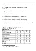
Humidistat
The
relay
of
the
humidistat
must
be
connected
as
NC.
Two
cases
can
be
distinguished:
1.
dehumidification
is
not
required
(activation
of
double
set
‐
point)
when
the
relay
is
de
‐
energized,
the
water
is
sent
to
the
floor
plant
(according
to
set
‐
point)
2.
dehumidification
is
required
(deactivation
of
double
set
‐
point):
when
the
relay
energie,
the
water
is
sent
to
the
fan
‐
coils
(first
set
point)
Relay:
T
he
3
‐
way
valve
can
be
connected
directly
to
the
field
mounted
relay
with
changeover
contact
(4A
resistives,
1
A
inductives,
230
VAC),
connecting
it
to
the
terminals
NC2,
N2,
NO2
(if
you
have
at
your
disposal
a
valve
with
3
contacts
for
power
supply),
or
to
the
terminals
N2
‐
NC2
(if
you
have
at
your
disposal
a
valve
with
2
electrical
contacts
for
power
supply
and
with
spring
return)
.
ON
time
of
the
relay
in
respect
of
tAr
Hy
Dew
point
Dew
point
+
odr
T
int
(°C/°F)
0
100
%
Output
odr
Содержание HPE Series
Страница 21: ......
Страница 29: ...28 ...
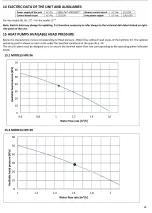
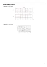
Страница 31: ...30 16 WATER PUMP CURVES 16 1 MODELS HPE 06 09 16 2 MODELS HPE 12 15 ...
Страница 34: ...33 19 3 HPE 12 15 IN OUT 1 M ...
Страница 35: ...34 20 WIRING DIAGRAMS 20 1 MODELS HPE 06 09 ...
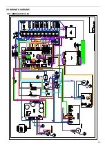
Страница 36: ...35 20 2 MODEL HPE 12 ...
Страница 37: ...36 20 3 MODEL HPE 15 ...
Страница 43: ...NOTE ...
Страница 44: ...NOTE ...
Страница 45: ...NOTE ...
Страница 46: ...NOTE ...
Страница 47: ......

