background image

2

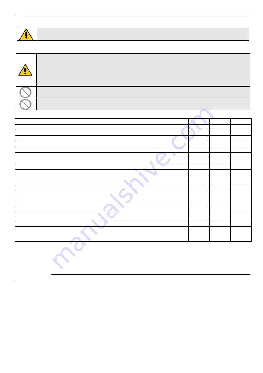
6


• Place


the


general


differential


circuit


breaker


to


"OFF"


position.

If


the


temperature


drops


below


0°C


there


is


serious


danger


of


frost:


add


a


mixture


of


water


and


glycol


in


the


system,


otherwise


drain


the


hydraulic


circuits


of


the


system


and


of


the


heat


pump.


11


MAINTENANCE


AND


PERIODICAL


CONTROLS


WARNING:


All


the


operations


described


in


this


chapter


HAVE


TO


BE


CARRIED


OUT


BY


TRAINED


STAFF


ONLY.


Before


any


operation


or


before


entering


the


inner


components


of


the


unit,


be


sure


that


the


power


supply


is


disconnected.


The


compressor’s


heads


and


discharge


piping


are


usually


at


high


temperature


levels.


Be


very


careful


when


operating


in


their


surroundings.


Aluminium


coil


fins


are


very


sharp


and


can


cause


serious


wounds.


Be


very


careful


when


operating


in


their


surroundings.


After


maintenance


operations,


re

install


the


cover


panels,


and


fix


them


by


means


of


screws.


The


refrigerant


circuits


must


not


be


filled


with


different


gas


other


than


that


indicated


on


the


nameplate.


The


use


of


a


different


refrigerant


can


cause


severe


damage


to


the


compressor.


It’s


forbidden


to


use


oils


other


than


those


specified


in


this


manual.


The


use


of


a


different


oil


can


cause


serious


damage


to


the


compressor.


It


is


a


good


rule


to


carry


out


periodic


checks


in


order


to


verify


the


proper


operation


of


the


unit.


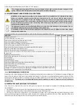
OPERATION


1


month


4


month


6


month


Filling


the


water


circuit.


x

Presence


of


bubbles


in


the


water


circuit.


x

Check


out


that


safety


and


control


devices


work


correctly


x

Check


out


possible


oil


leakage


from


compressor.


x

Check


out


possible


water


leakages


from


the


hydraulic


circuit.


x

Check


out


the


proper


working


of


the


flow


switches.


x

Check


out


that


the


crankcase


resistances


are


properly


supplied


and


functioning.


x

Clean


the


metallic


filters


of


the


hydraulic


circuit.


x

Clean


the


finned


coil


by


means


of


compressed


air


or


water


jet.


x

Check


out


that


all


the


terminals


on


the


electric


board


as


well


as


on


the


terminals


of


the


compressor


are


properly


fixed.


x

Tightening


of


water


connections.


x

Check


out


the


tightening


and


the


balancing


of


the


fan


blades.

x

Correct


voltage.


x

Correct


absorption.


x

Check


the


refrigerant


charge.


x

Check


the


operating


pressure,


and


superheat


and


subcooling

x

Check


of


the


efficiency


of


circulation


pump.

x

Check


the


expansion


tank.


x

If


the


unit


should


be


out


of


service


for


a


long


period,


discharge


water


from


the


piping


and


from


heat


exchanger.


This


operation


is


necessary


if,


during


seasonal


stoppages,


ambient


temperature


is


expected


to


go


down


below


the


freezing


point


of


the


employed


fluid.


x


11.1


ENVIRONMENTAL


PROTECTION


According


to


the


norms


dealing


with


the


use


of


depleting


stratospheric


ozone


substances,


it


is


forbidden


to


release


refrigerants


fluids


in


the


atmosphere.


They


have


to


be


collected


and


delivered


to


the


seller


or


to


proper


gathering


points


at


the


end


of


their


operating


life.


Refrigerant


R410A


is


mentioned


among


controlled


substances


and


for


this


reason


it


has


to


be


subjected


to


the


mentioned


norms.


A


particular


care


is


recommended


during


service


operations


in


order


to


reduce


as


much


as


possible


any


refrigerant


loss.


12


WHEN


THE


UNIT


GOES


OUT


OF


SERVICE


Once


the


unit


is


arrived


at


the


end


of


its


life


cycle


and


needs


to


be


removed


or


replaced,


the


following


operations


are


recommended:


• the


refrigerant


has


to


be


recovered


by


trained


people


and


sent


to


proper


collecting


centre;

• compressors’


lubricating


oil


has


to


be


collected


and


sent


to


proper


collecting


centre;

• the


frame


and


the


various


components,


if


not


serviceable


any


longer,


have


to


be


dismantled


and


divided


according


to


their

nature,


particularly


copper


and


aluminium,


which


are


present


in


conspicuous


quantity


in


the


unit.


These


operations


allow


easy


material


recover


and


recycling


process,


thus


reducing


the


environmental


impact.


Содержание HPE Series

Страница 1: ...User s and Installer s Manual HPE 06 15 INVERTER Chillers and inverter air water heat pumps with axial fans HPE 06 15 INVERTER ...

Страница 2: ... AND INVERTER AIR WATER HEAT PUMPS WITH AXIAL FANS Possible wasted electrical or electronic devices products should not be located together with normal domestic waste but disposed according to the current WEEE law in compliance with the European Directive 2002 96 EC and following modifications 2003 108 EC Please inform yourself at your local Administration or at your reseller in case the product w...

Страница 3: ...D MINIMUM TECHNICAL CLEARANCES 10 7 4 HYDRAULIC CONNECTIONS 10 7 4 1 Drainage connection 10 7 4 2 Service valve 11 7 4 3 Plant drainage system 11 7 4 4 Hydraulic circuit 11 7 5 REFRIGERANT DIAGRAM 12 7 6 ELECTRICAL CONNECTIONS 12 7 6 1 WIRING TERMINAL BLOCK 12 8 START UP 14 9 USER CONTROL INTERFACE 15 9 1 SETPOINT ADJUSTABLE BY THE USER 15 9 2 DISPLAY 15 9 3 LED 15 9 4 DYNAMIC SET POINT ADJUSTING ...

Страница 4: ... pressure 25 9 19 POWER FAILURE 25 9 20 USER BLOCK ALLARMS TABLE 25 10 SHUTDOWNS FOR LONG PERIODS 25 11 MAINTENANCE AND PERIODICAL CONTROLS 26 11 1 ENVIRONMENTAL PROTECTION 26 12 WHEN THE UNIT GOES OUT OF SERVICE 26 13 TECHNICAL DATA 27 14 ELECTRIC DATA OF THE UNIT AND AUXILIARIES 28 15 HEAT PUMPS AVAILABLE HEAD PRESSURE 28 15 1 MODELS HPE 06 28 15 2 MODELS HPE 09 28 15 3 MODELS HPE 12 29 15 4 MOD...

Страница 5: ...D TECHNICAL CHARACTERISTICS OF THE KIT 37 22 3 FUNCTIONS OF HUMIDISTAT 38 22 4 SETTING OF MINICHILLER 38 22 5 NOTES FOR INSTALLATION 38 22 6 ADJUASTABLE SET POINT 39 22 7 COMMUTATION 39 22 8 WIRING DIAGRAMS 40 22 8 1 Wiring diagram without external relay connection 40 22 8 2 Wiring diagram with external relay connection 40 22 9 HUMIDISTAT CONNECTION 41 22 10 HYDRAULIC DIAGRAM TYPE 41 4 ...

Страница 6: ...s of it delivered by the manufacturer as an attachment to this manual A2B Accorroni E G is available to give any detailed information about this manual and to give information regarding the use and the maintenance of its own units 1 2 GRAPHIC SYMBOLS Indicates operations that can be dangerous for people and or disrupts the correct operation of the equipment Indicates prohibited operations Indicate...

Страница 7: ... 89 391 CEE 89 686 CEE 89 655 CEE 86 188 CEE and 77 576 CEE directives Every employer shall implement such provisions and ensure that workers respect them Do not tamper with or replace parts of the equipment without the specific consent of the manufacturer The manufacturer shall have no responsibility whatsoever in case of unauthorised operations Using components expendable materials or spare part...

Страница 8: ... m for each of the two components Respiratory protection For rescue and maintenance operation in storage tanks use self contained respirator apparatus The vapors are heavier than air and can cause suffocation by reducing oxygen available for breathing Eyes protection Safety glasses Protection of hands Rubber gloves Hygiene measures Do not smoke PHYSICAL AND CHEMICAL PROPERTIES Colour Colourless Od...

Страница 9: ...7mm for the model 09 and 5 16 for the other models 12 and 15 the thickness of the aluminium fins is 0 1mm The tubes are mechanically expanded into the aluminium fins to improve the heat exchange factor The geometry of these condensers guarantee a low air side pressure drop and then the use of low rotation and low noise emission fans 5 5 FANS The fans are axial type with aluminium aerofoil blades T...

Страница 10: ... always modulating type it adopts asynchronous motor The hydraulic circuit also includes expansion vessel safety valve 6 bar and the automatic air release valve 5 11 FAN SPEED CONTROL This type of control is managed by the microprocessor and is necessary for optimizing the pressure of evaporation condensation during summer winter operation in order to allow proper running of the unit 6 AVAILABLE V...

Страница 11: ...e designed depending on the nominal water flow and on the hydraulic pressure drops of the system All pipes have to be insulated with closed cell material of adequate thickness Chillers have to be connected to piping by means of flexible joints Piping should include Hole thermometers to monitor the system s temperature Manual gate valves to separate the chiller from the hydraulic circuit Y shaped m...

Страница 12: ...y to drain the plant close at first the inlet and outlet manual gate valves not supplied and then remove the pipes that are disposed externally on the water inlet and on the water outlet in order to spill away the liquid contained in the unit for easier operation it is recommended to install externally two draining valves on the water inlet and on the water outlet between the unit and the manual g...

Страница 13: ...rce providing equipments as general magnetothermic circuit breaker differential circuit breakers for each electric line proper grounding for the plant etc Power cables electric protections and line fuses have to be sized according to the specifications listed in the wiring diagram enclosed with the unit and in the electrical data contained in the table of technical characteristics see Paragraph 13...

Страница 14: ...ct Power supply NO terminal 230V 50Hz 5A resistives 1 A inductives 3 way valve double set point for radiant panels optional to use only on V2 series see paragraph 21 for further configuration settings please refer to Paragraph 9 17 R Modbus signal connection to remote keyboard R Modbus signal connection to remote keyboard 12V Power output for remote keyboard 12V 50Hz 500mA 12V Power output for rem...

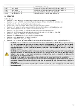
Страница 15: ...e is no refrigerant leakage Check out that all the cover panels are installed in the proper position and locked with fastening screws before start up WARNING The unit must be connected to the electrical network and should be in STAND BY mode powered closing the general switch in order to operate the crankcase heaters of the compressor for a minimum of 12 hours before start up the heaters are autom...

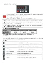
Страница 16: ...nitary Setpoint C San 48 25 55 The functionality of the second setpoint can be used only when you purchase the proper optional kit 9 2 DISPLAY In Normal view displays the outlet water temperature reported to tenths of degrees or the alarm code if at least an alarm is active In case of multiple alarms activation it will display the first alarm while the second appears when the first is reset Into t...

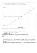
Страница 17: ...fset max in cooling mode operation b10 offset max in heating mode operation b11 Outdoor temperature setting in cooling mode b12 Outdoor temperature setting in heating mode b13 Temperature difference in cooling mode operation b14 Temperature difference in heating mode operation Curve of the set point variation as a function of the outside temperature 9 5 0 10V ANALOG INPUT FOR SET POINT REGULATION ...

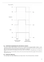
Страница 18: ... flow switch with manual reset The pump is always turned on if the antifreeze resistances are running or when the hydraulic pump operates in antifreeze mode is enabled if the water regulation temperature decreases below 8 C is disabled if the water regulation temperature increases above 10 C 9 6 1 OPERATION BY THERMOREGULATOR Default During this operating mode P03 1 default the thermoregulator act...

Страница 19: ...P16 in minutes activated when the pump is turned off for satisfied thermoregulation In the case of the activation of the flowswitch alarms with automatic reset the pump is still operating even if the compressor is off The periodic function is also interrupted in the case of the intervention of the antifreeze thermoregulator that constrains the opeartion of the pump 9 6 3 CONTINUOUS OPERATION In th...

Страница 20: ... valve can divert the water flow towards the sanitary tank After the water flow is diverted the compressor changes the frequency to the maximum value till the temperature reaches the set point of sanitary water Once reached the set point value the valve switches to the stand by mode and the compressor works normally When using a 3 way valve to switch over with 3 contacts for power supply it must b...

Страница 21: ......

Страница 22: ... for the plant the sanitary heater will operate only if the thermoregulation for the heater of plant side is accomplished 2 2 r20 1 the priority is for the sanitary the heater of the plant side will operate only if the thermoregulation of the sanitary heater is accomplished 9 15 ACTIVATION OF THE AUXILIARY ELECTRIC HEATERS DURING THE JOINT IN SUBSTITUTION OPERATION TO THE COMPRESSOR The compressor...

Страница 23: ...unit system side the digital outputs are at 230V AC therefore they must control a relay not included with free contacts The digital outputs are set when the value 31 is attributed to the parameters H58 or H61 or H62 The output is active during summer operation while is disabled in OFF mode or winter mode During sanitary hot water production and defrosting mode the output keeps the setting of the l...

Страница 24: ...oil of the contactor contact NO 230Vac H61 Open collector 1 configuration 6 0 32 I 0 input not assigned 6 sanitary water 3 way valve 22 auxiliary electric heater of the system 24 alarm 26 Sanitary water auxiliary electric heater 29 boiler For the correct connection to NC1 N1 NO1 terminals see paragraphs 22 8 1 and 22 8 2 It is necessary to use an external relay in order to reduce the total power c...

Страница 25: ...ay on activation of the auxiliary heaters of sanitary mode 15 0 255 I r20 Priority on use of heaters 1 0 1 I 0 priority for system side 1 priority for sanitary side The setting of this parameter is required only if r14 1 r21 Enabling the mitigation to system side with heaters in defrost 0 0 1 I 0 function disabled 1 function enabled r22 Set for the joint operation of auxiliary heaters compressor 7...

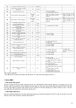
Страница 26: ...lower than value set from the controller as a function of operating mode and or of the model the alarm will be activated In this case the compressor will stop immediately The alarm will reset when the pressure goes over the set hysteresis 9 19 POWER FAILURE After power supply reset 1 The system comes back to the previous state before the power failure 2 If the system is defrosting this mode will b...

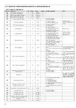
Страница 27: ...e finned coil by means of compressed air or water jet x Check out that all the terminals on the electric board as well as on the terminals of the compressor are properly fixed x Tightening of water connections x Check out the tightening and the balancing of the fan blades x Correct voltage x Correct absorption x Check the refrigerant charge x Check the operating pressure and superheat and subcooli...

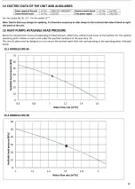
Страница 28: ...dB A m3 h kPa l kg HPE 06 6 2 2 30 5 67 1 49 3 80 A 5 0 1 80 4 44 1 53 2 90 B 6 5 2 40 5 99 1 46 4 10 A 5 8 2 10 5 35 1 64 3 26 A 4 16 Rotary 10 8 44 48 50 1 07 53 18 89 HPE 09 9 9 3 70 8 93 2 41 3 71 A 8 2 3 00 7 18 2 47 2 91 B 10 3 4 00 9 49 2 31 4 11 A 9 3 3 50 8 50 2 57 3 31 A 4 18 Rotary 230V 1 50Hz 18 8 45 50 53 1 85 33 25 103 HPE 12 13 2 4 60 11 90 3 12 3 82 A 10 8 3 70 9 53 3 27 2 92 B 13 ...

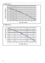
Страница 29: ...28 ...

Страница 30: ... 30 40 50 60 70 1 3 1 5 1 7 1 9 2 1 2 3 2 5 2 7 2 9 3 1 Available head pressure kPa Water flow rate m h 15 4 MODELS HPE 15 0 10 20 30 40 50 60 1 6 1 8 2 2 2 2 4 2 6 2 8 3 3 2 3 4 3 6 Available head pressure kPa Water flow rate m h ...

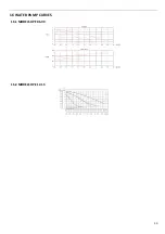
Страница 31: ...30 16 WATER PUMP CURVES 16 1 MODELS HPE 06 09 16 2 MODELS HPE 12 15 ...

Страница 32: ...contact our company for the feasibility study and evaluation of changes to be made according to your requests The maximum temperature that can be maintained at the outlet of the evaporator is 25 C Higher temperatures up to a maximum of 40 C can anyway be tolerated during transitions and start up phases of the system In all cases the maximum electrical input occurs for the heat pump operating mode ...

Страница 33: ...F Pressure drops correction factor The water flow rate and pressure drop correction factors are to be applied directly to the values given for operation without glycol The water flow rate correction factor is calculated in order to get the same temperature s difference that would be obtained without glycol The pressure drops correction factor takes into account the different water flow rate obtain...

Страница 34: ...33 19 3 HPE 12 15 IN OUT 1 M ...

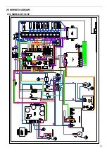
Страница 35: ...34 20 WIRING DIAGRAMS 20 1 MODELS HPE 06 09 ...

Страница 36: ...35 20 2 MODEL HPE 12 ...

Страница 37: ...36 20 3 MODEL HPE 15 ...

Страница 38: ...minal board 22 DOUBLE SET POINT KIT OPTIONAL ACCESSORY 22 1 PURPOSE AND SCOPE The function of double set point is consisting of introducing a second working set point of the plant side in both cooling and heating modes The field of application is mainly that of the floor cooling assisted by fan coil for dehumidification The purpose of the application is to avoid the conditions of formation of cond...

Страница 39: ...ears of selection on CRH 1 Classic mode 2 Double set point active in the summer 3 Double set point active in the winter 4 Double set point active in both summer and winter 22 5 NOTES FOR INSTALLATION Humidistat The relay of the humidistat must be connected as NC Two cases can be distinguished 1 dehumidification is not required activation of double set point when the relay is de energized the water...

Страница 40: ...ed must be connected to the floor plant In the case of a 3 way valve with 3 contacts for power supply the way of the valve that is hydraulically connected to the floor plant must be activated as shown in the wiring diagrams presented in the paragraph 22 8 In this wiring diagrams show the direction of the water flow to divert by valve to either floor side or plant side In these wiring diagrams as f...

Страница 41: ...agrams as for boiller side plant floor plant or fan coil side it s intended on which way the valve will be diverted when it s activated 22 8 1 Wiring diagram without external relay connection 22 8 2 Wiring diagram with external relay connection ...

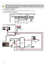
Страница 42: ...OFF the external breaker of the electrical power when the unit should be maintened 22 9 HUMIDISTAT CONNECTION Carry out the following connections between the humidistat and the terminal block of the minichiller unit Connect POWER SUPPLY to 12V and 12V Connect RELAY C NC to the two terminals SE 22 10 HYDRAULIC DIAGRAM TYPE Floor plant thermo accumulator Aqueduct MSI Minichiller Inverter 3 way valve...

Страница 43: ...NOTE ...

Страница 44: ...NOTE ...

Страница 45: ...NOTE ...

Страница 46: ...NOTE ...

Страница 47: ......

Страница 48: ...A2B Accorroni E G s r l Via d Ancona 37 60027 Osimo An Tel 071 723991 r a Fax 071 7133153 web site www accorroni it e mail a2b accorroni it ...

Отзывы: