


42
78-8130-6151-8 Rev G
Note: This 15.2 cm (6-inch) rise must be exact for the depth reading to be accurate.
A suggestion is to utilize a 15.2 cm (6 inch) piece of plastic pipe or wood as a spacer
between the ground and the tip of the receiver for this precise measurement.
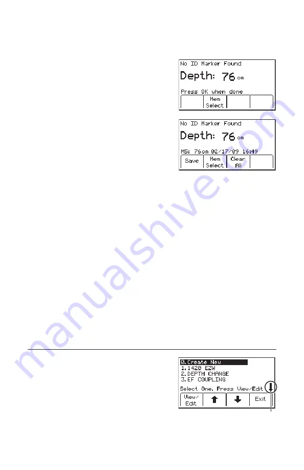
3. Raise the receiver 15.2 cm (6 inches). Press the
Depth
[SK] key again. The estimated depth of
the marker from ground level will be displayed.
−
Five depth readings can be saved with the
time and date.
4.
To access the memory locations, press
Mem
Select
[SK].
−
Save [SK] will place each entry in sequential
order in memory (M1–M5) until five
readings have been stored. The receiver will
overwrite saved entries in excess of five,
beginning with M1.
5. Optional: Press
Clear All
[SK] to delete all stored depth information.
6. Press
Mem Select
[SK] to select a specific memory location (M1-M5) to store the
depth readings. When the preferred location appears on the display, press
Save
[SK]. The display and memory location will populate with the current information.
7. Each memory location can be reviewed by pressing
Mem Select
[SK Toggle].
8. Press
Locate/OK
[5] to return to Marker Locate Mode.
14. Creating/Editing Templates for 3M
™
iD Markers
In the User Template screen, the operator can create and modify templates for writing
to iD markers. Note that the easiest way to create user templates is by using the 3M™
Dynatel™ PC Tool Kit software on a PC and then downloading them to a receiver via
the RS232
Serial Port
[15] ([14] on 2250M Receiver) on the receiver and the provided
RS232 cable or RS232-to-USB adapter cable. The 3M™ Dynatel™ PC Tool Kit
software is available free of charge at www.3M.com/dynatel under the Software section;
2550/2573/2250M/2273M/1420 Locator PC Tools xx.x.x (EXE xx.xMB).
A. Creating New Templates
1. Select
Create New
by pressing the up/down
arrows [SK].
2. Press
View/Edit
[SK].
This arrow indicates that additional
viewable information is available
by pressing the down arrow [SK].


