background image


92 

=

 Image Server 2000 

other applicable laws of the United States.  You acknowledge that the Software design remains a 

confidential trade secret of Company.  Failure to comply with the above restrictions will result in 
automatic termination of this license and will make available to Company other legal remedies.  You 

may not disclose any of Company’s proprietary or trade secret information relating to the Software to any 

third party. 


4.  Company warrants that the Software will perform substantially in accordance with its Documentation.  

Your exclusive remedy for breach of this limited warranty and Company’s entire liability shall be, in 

Company’s discretion, either return of the price paid to Company by You for the Software, or repair or 

replacement of the Software after Software and Documentation are returned to Company with an 
applicable receipt.  Company’s warranty is void if failure of the Software has resulted from accident, 

abuse, modification or misapplication.  COMPANY MAKES NO OTHER WARRANTIES, EXPRESS OR 

IMPLIED, WITH RESPECT TO THE SOFTWARE AND DOCUMENTATION, AND SPECIFICALLY 

DISCLAIMS THE IMPLIED WARRANTIES OF MERCHANTABILITY AND FITNESS FOR A PARTICULAR 
PURPOSE.  COMPANY DOES NOT WARRANT THAT THE OPERATION OF THE SOFTWARE WILL BE 

UNINTERRUPTED OR ERROR FREE. 


5.  TO THE MAXIMUM EXTENT PERMITTED BY LAW, IN NO EVENT SHALL COMPANY BE LIABLE FOR 

ANY SPECIAL, INCIDENTAL, CONSEQUENTIAL OR PUNITIVE DAMAGES WHATSOEVER, 

INCLUDING ANY CLAIMS FOR LOST PROFITS, BUSINESS INTERRUPTION, LOST INFORMATION 

OR OTHER DAMAGES ARISING OUT OF THE USE OR INABILITY TO USE THE SOFTWARE.  IN ALL 

EVENTS, COMPANY’S SOLE OBLIGATION OR LIABILITY UNDER THIS LICENSE IS THE 
REPLACEMENT OR REPAIR OF THE SOFTWARE OR A REFUND OF THE PURCHASE PRICE. 


6.  You may terminate the license granted in Section 1 of this Agreement at any time by destroying or 

erasing your copy of the Software.  Company may terminate this Agreement immediately and without 

notice if you fail to comply with any term or condition of this Agreement.  In the event of termination of 

this Agreement, all the sections of this Agreement will survive except for Section 1. 


7.  This Agreement shall be governed by and construed in accordance with the laws of the State of 

California, U.S.A., without reference to conflicts of laws provisions or the 1980 U. N. Convention on 

Contracts for the International Sale of Goods and, as to matters affecting copyrights, trademarks and 

patents, by U.S. federal law.  Any dispute with respect to this Agreement shall be brought and heard 
either in the California state courts located in Los Angeles County, California, or the federal district court 

for the Central District, Western Division, located in Los Angeles, California.  In such event, the parties 

to this Agreement each consent to the 

in personam

 jurisdiction and venue of such courts.  The parties 

agree that service of process upon them in any such action may be made if delivered in person, by 

courier service, by telegram, by facsimile or by first class mail, and shall be deemed effectively given 

upon receipt. 


8.  This Agreement sets forth the entire agreement between You and Company pertaining to the licensing of 

the Software, and supercedes in its entirety any and all written or oral agreements previously existing 

between the parties with respect to such subject matter.  If any provision of this Agreement is held 

invalid or unenforceable, such provision shall be revised to the extent necessary to cure the invalidity or 
unenforceability, and the remainder of this Agreement shall continue in full force and effect.  In the 

event of any conflict between any provision of this Agreement and applicable law, the provisions of this 

Agreement affected shall be modified to remove such conflict and permit compliance with such law, and 

as so modified this Agreement shall continue in full force and effect.  This Agreement may not be 
assigned without the consent of Company. 

Содержание V2000 Series

Страница 1: ...O P E R A T I O N S manual I M A G E S E R V E R 2 0 0 0 Model V2000...

Страница 2: ...For use with Software Version 1 16 Image Server Model V 2000 June 2004 Copyright 2003 2004 360 Systems All rights reserved Printed in the United States of America...

Страница 3: ...0 Available Models and Options 11 Installation ________________________________________________________ 13 Unpacking 13 Package Contents 13 Rack Mounting 14 Software 14 The Image Server 2000 Hardware...

Страница 4: ...8 Edit while Recording 38 The DV and Graphics Option_________________________________________ 41 Importing TARGA Graphics Files 41 Animation Import 41 FTP File Transfers 42 Key Fill Mode 42 Still Fram...

Страница 5: ...ilding a Degraded Array 68 Replacing Hard Drives 70 Networking________________________________________________________ 71 MXF File Ingest 71 Network Operations 71 Using the Image Server in a Large Net...

Страница 6: ...User License Agreement__________________________________________ 91 For IMAGE SERVER 2000 Software 91 Appendix A________________________________________________________ 93 Connector Specifications 93...

Страница 7: ...duce new product features not explained in earlier versions of the operations manual When such revisions are shipped in the form of a CD ROM printed operational notes will be included When revisions a...

Страница 8: ...o avoid personal injury or equipment damage Only qualified personnel should perform installation and service Refer to appropriate sections of this product manual for instruction Contact 360 Systems Cu...

Страница 9: ...lean server only with a soft cloth dampened with water Do not spray cleaners or solvents directly on the product CAUTION Replace battery only with the same or equivalent type BR and CR Lithium batteri...

Страница 10: ...4 Image Server 2000...

Страница 11: ...ent Its dual analog and digital personality helps it fit seamlessly into an existing analog facility or become part of a new digital build out Exceptional Storage Capacity The Image Server s program s...

Страница 12: ...m flexibility 360 Systems Automation Partners provide controllers for applications ranging from low cost systems for public access and educational programming up to large scale broadcast solutions Con...

Страница 13: ...y a standard keyboard and pointing device supplied and requires only a VESA compliant VGA or SVGA monitor or flat panel display The GUI displays a virtual control panel for each server channel which i...

Страница 14: ...e understand quality and reliability and we ve paid close attention to design issues like power cooling and protecting stored data We ve also included alarms on key server components When the very hig...

Страница 15: ...deo inputs and outputs Includes balanced analog and AES EBU digital audio ports as standard equipment Four audio channels 2 AES stereo pairs for each video channel Serial control via VDCP P2 or Odetic...

Страница 16: ...Automated capture of satellite tape microwave and fiber feeds FPT File Delivery Deliver news promos spots over DSL or ATM lines Play to Air Server Playback under automation control Program Store and F...

Страница 17: ...and graphics with simultaneous key and fill Direct FTP file import from Photoshop After Effects Final Cut Pro Newscutter or Xpress DV Pro May be added to an existing Image Server 2000 or ordered as a...

Страница 18: ...RC 235 aside when not needed The infrared receiver plugs into the Image Server 2000 keyboard jack and may be positioned for best pickup from the keyboard 88 keys numeric keypad 12 function keys Full f...

Страница 19: ...50mm of space between the product and outer container The corners of the product must be protected Package Contents Confirm that all items on the packing list have been received Contact 360 Systems i...

Страница 20: ...y the rack mounting rails Do not support substantial cable weight from the Image Server Keep the air vent slots on the sides of the Image Server free of obstructions Remove the front panel to expose t...

Страница 21: ...tarily will cause the system to begin an orderly shutdown In the event that the system has stopped responding to commands and will not shutdown hold the button in for 4 seconds to force a power down D...

Страница 22: ...TC time code output 17 3 SDI video outputs 18 SDI Video Input 1 3 RS 422 serial control ports 2 6 XLR 3 audio outputs AES EBU digital or 4 balanced analog 3 2 XLR 3 audio inputs AES EBU digital or 4 b...

Страница 23: ...the transition from an analog studio to digital broadcasting and assures that the server can operate with virtually any other equipment Note that both analog and digital audio are not available at th...

Страница 24: ...nfiguration on the rear panel After the jumpers are set apply appropriate Analog or Digital labels above the corresponding connectors on the rear edge of the top cover Serial Control Ports Each of the...

Страница 25: ...lack As with all video systems this server and equipment connected to it must be referenced to a common genlock source The GENLOCK input provides a fixed 75 ohm termination An internal crystal referen...

Страница 26: ...els This is best viewed on 17 inch monitors 360 Systems does not provide monitors for the server Note Do not use older monitors that do not state they are VESA compliant Serial Port The system board s...

Страница 27: ...r system graphic interfaces There is a task bar and start menu at the bottom of the screen The Image Server desktop is always running while the machine is on Use the Start menu button to launch applic...

Страница 28: ...rily pressing the front panel power button or through the On Screen user interface Keyboard Shortcuts Most operations of the On Screen user interface can be performed using keyboard shortcuts See the...

Страница 29: ...he Image Server internal system date and time This information will be used to time stamp the data files of new recordings Channels Select a video channel from this dropdown menu to configure channel...

Страница 30: ...t Up to three Channel Transport Windows may be opened at once one per server channel The Window menu may be used to arrange the channel windows on the screen Windows may also be arranged manually by u...

Страница 31: ...h naming the new clip The New menu choice opens a dialog box in which a new clip may be named Figure 5 Clip names can include any alphanumeric ASCII character up to 32 characters Note File naming is c...

Страница 32: ...Figure 6 A new selection closes the previously open clip and the newly selected clip becomes ready for playout or trimming Refer to the following main section titled Playing a Clip for more informati...

Страница 33: ...pt to enter a clip name After entering the name click SAVE AS again to save the clip with a new name When using SAVE AS it is a good practice to give new sub clips a name related to the original A cli...

Страница 34: ...ve As Renaming clips will never cause the Image Server to lose track of its relationship to the original recorded data The original recording will remain on the disk as long as there is at least one c...

Страница 35: ...ons are currently in progress The Status Bar A status bar appears at the bottom of the window that provides system information to the user Messages such as CONNECTED TO HOST or CONNECTION TO HOST REFU...

Страница 36: ...l 1 is switched between Play Ready and Record Ready modes The status display will report Ready when the new mode is available NOTE 1 An external genlock signal must be connected to the server to make...

Страница 37: ...toggled while the channel is in playlist mode When E E is ON the video input signal is routed to the CVBS and SDI outputs of Channel 1 Manually toggle the E E mode button OFF to switch the output to...

Страница 38: ...the mouse button down The cursor may now be moved over the Stop button to wait for the desired point When using a scroll mouse position the cursor over the slider control scale and rotate the wheel t...

Страница 39: ...be applied to the rear panel genlock connector The server will not enter record mode if it does not detect the presence of a genlock signal The genlock input has a fixed 75 ohm termination Do not add...

Страница 40: ...DI C Click on APPLY or OK to confirm the selection and close the window These topics are covered in detail in the System Configuration chapter Making a Recording When the steps outlined in Setting up...

Страница 41: ...ach is valuable if Channels 2 and 3 are in use for another purpose If Channel 2 or 3 is available it can be used to play the recording while it is being made A short delay is required before a clip be...

Страница 42: ...erify that the status windows displays IDLE C From the main menu bar select SYSTEM CONFIGURE D Select GENLOCK as the sync source E Click APPLY followed by OK The Configure window will close F Check th...

Страница 43: ...Click PLAY to play the clip 6 Click STOP at any time 7 Additional clips can be played by following steps 3 through 5 Additional channel transport windows can be opened and multiple clips can be played...

Страница 44: ...ding on either Channel 2 or 3 by selecting the clip name from the File Open menu Note that recordings must be 10 seconds long before they appear in the clip list Use the transport controls to select a...

Страница 45: ...r keyboard arrows to move between fields When a field is highlighted increment the up down arrows spinwheels to change a numeric value Whether or not a clip is still or playing press Mark Out to captu...

Страница 46: ...before the Mark Out point or EOM if no Mark Out Point exists and then begin playback Review Out will stop at the Mark Out Point After Review Out commences all of the standard transport buttons are ava...

Страница 47: ...and a Key frame if it exists These will be converted to high resolution MPEG 2 files one frame in length For example if an original file is named Logo tga the MPEG 2 files created will be named Logo m...

Страница 48: ...ill be written into a 24 bit space MXF Material Exchange Format mxf Transfer of MXF files between compatible products is the preferred method of file interchange to and from an Image Server 2000 360 S...

Страница 49: ...utomation system must issue a Still command to Channel 2 to achieve this effect Ingesting a TARGA file via FTP automatically creates a key clip and a fill clip each a single frame in length For exampl...

Страница 50: ...44 Image Server 2000...

Страница 51: ...n screen This window is where playlists are created edited named and saved Playlists are not linked to a particular channel they are saved into a playlist folder and may be selected from any channel f...

Страница 52: ...ll will appear as 1 frame in the clip list When a still is encountered the playlist will pause and hold the still image until a Play command is issued at which point the playlist will continue to the...

Страница 53: ...enu select RENAME This action will open a dialog box in which a new playlist name can be entered Deleting a Playlist From the File Menu select DELETE This action will present a list of named playlists...

Страница 54: ...name and the total running time for the entire list appears above the clip window Click PLAY to run the playlist During playback the time remaining appears in the upper right window Click PAUSE to mo...

Страница 55: ...his clip Ignored Resume this clip STOP Terminate this clip advance to next clip and hold Terminate this clip advance to next clip and hold Terminate this clip advance to next clip and hold Figure 12 E...

Страница 56: ...50 Image Server 2000...

Страница 57: ...rol the operation of all Image Server channels Controller Priority In general the first controller to gain control of a video channel will have exclusive command This prevents conflicting instructions...

Страница 58: ...isplay the first frame of video Cue w Offset vs Timestamp When checked the time code for the clip becomes zero based with reference to the head point To move to the head point of the clip the automati...

Страница 59: ...e Server has been tested by 360 Systems and found to be compatible with the following controllers This list is not comprehensive and the inclusion or absence of a product does not indicate a preferenc...

Страница 60: ...eral good uses it may be put to that take only a small amount of extra work and resources and enhance overall system capability A fully functional wired and running backup channel in the event of a pr...

Страница 61: ...his dialog window to set the Image Server internal system date and time This information will be used to time stamp the data files of new recordings All channels must be idle to change the Date Time s...

Страница 62: ...lock Timing Lines 4 to 12 Pels 200 to 200 Output Mode 2 or 3 Channel Figure 14 System Timing Configuration Window Video Sync During normal operation the Image Server must be referenced to an external...

Страница 63: ...oggle button advances the phase of all channels by 180 degrees with respect to the external genlock signal PAL Models The Color Framing toggle button advances the phase of all channels in four 90 degr...

Страница 64: ...dent function and channel assignments for each GPI input Assignable functions include Play Stop Re cue Record and Pause Each may be mapped to Channel 1 Channel 2 Channel 3 Channels 1 2 Channels 2 3 or...

Страница 65: ...low Two drop down menus provide independent function selection for each output Available choices include Idle Playing and Recording Each of these states may be monitored for Channel 1 Channel 2 Chann...

Страница 66: ...60 Image Server 2000 Time Code Type The Image Server 2000 uses drop frame time code for NTSC operations Figure 17 Time Code Configuration Window...

Страница 67: ...ore recording the change will not be applied to this recording Do not make changes to a recording s characteristics after you have initiated it Input Configuration The factory default settings for Inp...

Страница 68: ...oice of zero or two audio channels is available With digital audio a choice of zero two or four channels may be made Since the Image Server records 24 bit uncompressed PCM a worthwhile saving of disk...

Страница 69: ...ow when E E mode is monitoring the input source and no clip is cued When recording begins E E mode switches the monitor from the input to the disk and the Time Code burn in window shows the current ti...

Страница 70: ...tion are effective immediately Changes to the Audio Slip will be effective when the clip is reloaded Figure 20 Channel Output Configuration Window Time Code Burn In This area of the dialog window sets...

Страница 71: ...ndisturbed In addition the Image Server 2000 uses Advanced Data Protection features where all drive commands are checked to ensure that no command corruption has taken place over the entire data path...

Страница 72: ...mage Server s Disk Array Configuration Utility provides tools for monitoring and managing the disk array Monitoring and troubleshooting programs automatically check the array and report problems The I...

Страница 73: ...art the initialization process as a background task This task should not interfere with Image Server s ability to record or play clips Parity errors may occur if the Image Server loses power or is imp...

Страница 74: ...a Port in the RAID Status window has a prior record of degrading or has failed to properly rebuild in a prior attempt 360 Systems recommends drive replacement The following steps initiate a manual arr...

Страница 75: ...degraded drive so that it is again selected 6 Click the Add Drive button 7 Click all of the Ports listed for the array Figure 25 Figure 25 Check Mark All Drives in the Array 8 Click Rebuild Unit 9 Cli...

Страница 76: ...s automatically updated every 5 minutes it does not do so Press Ctrl R to update the page and percentage complete information Replacing Hard Drives The Image Server hard disk drives have been factory...

Страница 77: ...y Image Servers at once and does not tie up the Image Server GUI which may already be in use Third party FTP manager programs are readily available for download through the Internet FTP programs may a...

Страница 78: ...ient application Windows Explorer FlashFXP etc to ask the user if they want to overwrite a file Interrupted and Resumed Transfers If a transfer is interrupted for example by a dropped connection the a...

Страница 79: ...tween Image Servers and graphics workstations without modification MPEG 2 mp2 mpg mpeg m2v The Image Server will ingest valid MPEG 2 program or elementary streams The server s ingest application will...

Страница 80: ...Mbps 10 OFF 100 GREEN 1000 YELLOW Yellow 1 000 Mbps Redundant Connections The two Gigabit Ethernet connections on the Image Server may be used for redundant connections Connecting more than one will n...

Страница 81: ...he connection It also means that there is only one IP Address for a given volume of data Figure 28 Network Configuration Tab Network Settings Tab Use the Image Server 2000 graphic user interface to co...

Страница 82: ...dows Host Name IP Address Net Mask Default Router Host Name may be a fully qualified domain name such as edit1 mydomain com All other manually configured addresses must be properly formatted IP addres...

Страница 83: ...indicates that there is a fault in the system power supply Shut down the Image Server and contact 360 Systems Customer Support for further hardware diagnosis FANS FLASHING indicates that there is a fa...

Страница 84: ...J 45 connector has integrated LED indicators to provide link status information The operation of the indicators is described below LED Color LED State Meaning Green Off 10 Mb link speed On 100 Mb link...

Страница 85: ...le undoing the screws Since the loosened screws are captive you may use them to pull the panel away from the chassis To re install the front panel tuck all wires into the chassis and move the face pan...

Страница 86: ...erboard Be sure each board is aligned with its slot in the mating connector before installing Use care to not flex any PC boards Interface cable connectors must be mated carefully Use care to not bend...

Страница 87: ...en remove the 6 32 x pan head Phillips screw holding the RAID card to the rear panel While supporting the riser card gently pull the RAID card from the riser card When the card is clear of the PCI ris...

Страница 88: ...etup Both jumpers for each channel Left Right or Main Aux must be set together either analog or digital Setting and calibration reference designations Connector Main 3 L Main 3 R Main 2 L Main 2 R Mai...

Страница 89: ...4 dBu output level 3 While observing the output level of audio Channel 1 Left adjust trimmer RV4 until a level of exactly 4 00 dBu is obtained 4 Repeat this procedure for audio Channel 1 Right while...

Страница 90: ...ure 6 Position all audio output jumper blocks to obtain analog outputs 7 Using the On Screen graphic user interface verify that server Channel 1 is in E E mode so that an input signal will appear at i...

Страница 91: ...Installer from the menu 6 The Installer menu provides a choice to Update the Image Server operating system begin a new complete install or cancel the install Choose UPDATE if you want to keep the vide...

Страница 92: ...on all drives 1 Turn system power OFF with the front panel button After it has shut down turn off the AC power switch and unplug the AC power cord 2 Remove the front panel as described above 3 Unscrew...

Страница 93: ...nal or equivalent packaging Call 360 Systems for a return authorization number before returning a product Use the following address for shipping and correspondence 360 Systems offices are open Monday...

Страница 94: ...ns are published in the Laser Product Performance Standard Code of Federal Regulation CFR Title 21 Subchapter J The International Electrotechnical Commission IEC Standard 825 Radiation of Laser Produc...

Страница 95: ...1 This device may not cause harmful interference and 2 this device must accept any interference received including interference that may cause undesirable operation Radio Interference Canada English...

Страница 96: ...nger available 360 Systems will replace it with a similar product or if not available a product of equal value Disclaimer and Limitation of Liability The liability of 360 Systems under the foregoing w...

Страница 97: ...erms and conditions of this Agreement The license to use the Software is conditioned upon Your compliance with the terms of this Agreement You shall be solely responsible for installation of the Softw...

Страница 98: ...of the Software Company may terminate this Agreement immediately and without notice if you fail to comply with any term or condition of this Agreement In the event of termination of this Agreement all...

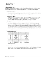
Страница 99: ...ELD FRAME GROUND 2 OR HOT DIGITAL 3 OR COMMON DIGITAL SHELL FRAME GROUND FRAME GROUND Serial Control Connector Pinout Pin EIA 422 DB9 F Connector 1 GND 2 Transmit A TX 3 Receive B RX 4 GND 5 N C 6 GND...

Страница 100: ...erver Six general purpose outputs also appear on the GPI connector These open collector outputs may be used as status outputs or may be used to drive an external LED or control input Refer to the conn...

Страница 101: ...5 GPO 5 12 GPO 4 24 GPO 3 11 GPO 2 22 INPUTS OUTPUTS 5V 200mA MAX SOURCE GPI O DB25 F 1K INTERNAL CIRCUITS 1K 15 2 3 16 1K 4 17 1K 5 18 1K 6 19 1K GPO 1 23 GPI 2 RTN GPI 2 GPI 3 RTN GPI 3 GPI 4 RTN GP...

Страница 102: ...ay be connected to the Image Server VGA adapter port Use only the 15 pin video port located on the graphics adapter card Do not use the video connector labeled MONITOR located below the GPI connector...

Страница 103: ...ct ID 04 ACK 0X 8X 16 Undelete Protect ID 04 ACK CMD 1 CMD 2 NAME CMD 1 CMD 2 NAME 1X 00 Stop 04 ACK 1X 01 Play 04 ACK 1X 02 Record 04 ACK 1X 04 Still 04 ACK 1X 05 Step 04 ACK 1X 06 Continue 04 ACK 1X...

Страница 104: ...st 3X 91 List of ID s 3X BX 14 ID Size Request 3X 94 ID Size 3X BX 16 ID Request 3X 96 ID Presence 3X 17 Compression Settings Request 3X 97 Compression Settings 3X BX 18 ID s Added List 3X 98 List ID...

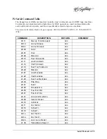
Страница 105: ...DEVICE TYPE REQUEST ACK 00 1D LOCAL ENABLE ACK 00 0C LOCAL DISABLE ACK 20 00 STOP ACK 20 01 PLAY ACK 20 02 RECORD ACK 20 10 FAST FORWARD ACK 2X 11 JOG FORWARD ACK 2X 12 VAR FORWARD ACK 2X 13 SHUTTLE F...

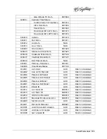
Страница 106: ...IME CODE PRESET ACK 44 31 PRE ROLL TIME PRESET ACK 41 33 SERVO REFERENCE SELECT ACK N A TIMER MODE STATUS ACK 7X 20 STATUS DATA 7X 20 N A COMMAND SPEED SENSE 71 2E 40 48 REF VIDEO SELECT ON ACK 40 49...

Страница 107: ...K 0X2001 PLAY ACK 0X2002 RECORD ACK 0X2004 STAND BY OFF ACK 0X2005 STAND BY ON ACK 0X200D DMC START ACK COMMAND HAS NO EFFECT 0X200F EJECT ACK 0X2010 FAST FORWARD ACK 0X2X11 JOG FORWARD ACK 0X2X12 VAR...

Страница 108: ...0X4X35 COLOR FRAME SELECT ACK COMMAND HAS NO EFFECT 0X4X36 TIMER MODE SELECT ACK 0X4X37 INPUT CHECK ACK 0X4040 AUTO MODE OFF ACK 0X4041 AUTO MODE ON ACK 0X4046 VARIABLE MEMORY OFF ACK 0X4047 VARIABLE...

Страница 109: ...6 0XA001 AUTO SKIP ACK ODETICS COMMAND 0XAX02 CUE UP TO RECORD ACK ODETICS COMMAND 0XAX04 PREVIEW IN PRESET ACK ODETICS COMMAND 0XAX05 PREVIEW OUT PRESET ACK ODETICS COMMAND 0XA006 PREVIEW IN RESET AC...

Страница 110: ...owest bit rate available 2 Mb s Video sync reference Genlock External black burst or internal crystal Audio Digital Inputs Outputs 2 stereo pairs 4 channels per video input or output Digital audio for...

Страница 111: ...Network port 2 Gigabit Ethernet File transfer protocol FTP Disk Storage Storage time max 100 hours max 4 x 250 GB drives at 12 Mb s Capacity 480 GB to 1 TB Data redundancy Hardware generated RAID 5 ut...

Страница 112: ...hift E E E Toggle Shift L Loop Toggle Shift C Local Toggle Shift J Eject Right Arrow Jog forward 1 frame Left Arrow Jog reverse 1 frame File Operations Playlist Ctrl N New Home Recue Ctrl O Open Space...

Страница 113: ...Index 107 APPENDIX D Mechanical Drawing 16 85 428 mm 16 12 409 mm 17 00 432 mm 19 00 483 mm 3 47 88 mm Mechanical Drawing Figure 31...

Страница 114: ...k Out Point 39 Play 30 Record 30 Review Clip 39 Review Out Point 40 Rew 31 Stop Still 31 Calibration Audio Level 81 Cascade Windows 23 24 CD ROM 83 CD ROM Drive 13 Channel Status Bar 29 Channels Menu...

Страница 115: ...isk Array 63 Hard Drive Replacement 84 I O Card Accessory 78 RAID 79 Video 79 Image Server Audio A D Selection 17 Audio I O 16 Connectors 15 16 Indicators 14 Models 10 Mounting 13 Rear Panel 15 16 Vid...

Страница 116: ...ram Updates CD ROM 83 Protocol 49 Rack Mounting 13 Radio Interference Compliance 86 RAID Card 79 Disk Array 63 Fault Tolerance 63 Performance 63 Repair 64 Rear Panel Drawing 15 16 Features 15 16 Indic...

Страница 117: ...In 62 LTC 18 Type 54 58 VITC 61 Timing Tab 54 Top Cover Removing 77 Track Arming 60 Transfer Rate Ethernet 69 Transport Menu 23 Trouble Shooting See Fault Diagnostics Variable Bit Rate 61 VDCP Command...

Отзывы: