


94
=
Image Server 2000
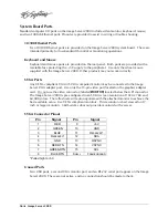
GPI Connector
A General Purpose Interface (GPI) connector (DB-25-F) is provided on the rear panel. Its six
inputs are optically isolated from the Image Server circuitry; individual floating input returns
are provided. +5 volts may be sourced from pins 21 or 22, or provided from an external
source. A current limiting device is provided within the Image Server.
Six general purpose outputs also appear on the GPI connector. These open-collector outputs
may be used as status outputs, or may be used to drive an external LED or control input.
Refer to the connector pin-out table and partial schematic, following.
GPI Connector Pinout
Pin
Signal
Pin
Signal
1
INPUT 1
14
INPUT 1 RTN
2
INPUT 2
15
INPUT 2 RTN
3
INPUT 3
16
INPUT 3 RTN
4
INPUT 4
17
INPUT 4 RTN
5
INPUT 5
18
INPUT 5 RTN
6
INPUT 6
19
INPUT 6 RTN
7
N/C
20
N/C
8, 9, 10
GND
21, 22
+5V S
OURCE
(200
M
A
MAX
)
11
OUTPUT 2
23
OUTPUT 1
12
OUTPUT 4
24
OUTPUT 3
13
OUTPUT 6
25
OUTPUT 5
Содержание V2000 Series
Страница 1: ...O P E R A T I O N S manual I M A G E S E R V E R 2 0 0 0 Model V2000...
Страница 10: ...4 Image Server 2000...
Страница 50: ...44 Image Server 2000...
Страница 56: ...50 Image Server 2000...