


47
UC5e IM Rev 2-1 July 2004
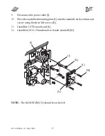
16.
Mount the deypad PCB [A], part number VU5E10005 onto the standoff
on the right and secure with a M3 x 6mm screw [B] supplied.
17.
Locate the 8-pin ribbon cable [C], part number VU5E10002. Connect
the white pin connector end to the upright connector on the deypad PCB
and the loose 4 x 2 pin connectors onto the UC5E main board.
NOTE: Connectors 1 & 4 are sensitive to polarity. These connectors
should be plugged in with the viewable pin sides (2 x gold col-
oured pins) facing outwards and the solid sides facing each other.
[A]
[B]
[C]


