background image

22

UC5e IM Rev 2-1 July 2004

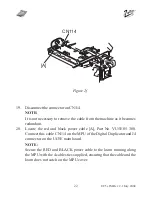
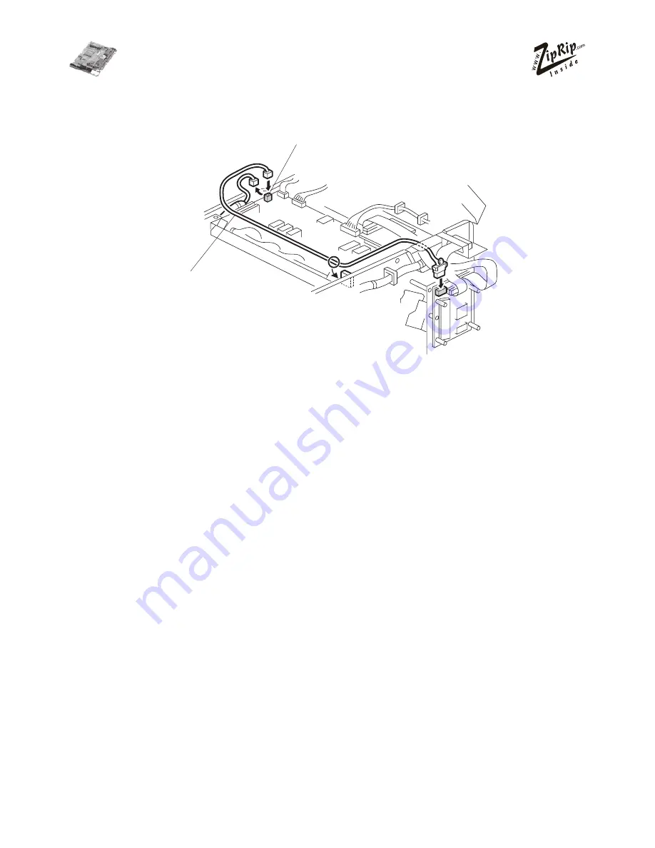
19.

Disconnect the connector on CN114.

NOTE:

It is not necessary to remove the cable from the machine as it becomes
redundant.

20.

Locate the red and black power cable [A], Part No. VU5E 05 300.
Connect this cable CN114 on the MPU of the Digital Duplicator and J4
connector on the UC5E main board.

NOTE:

Secure the RED and BLACK power cable to the loom running along
the MPU with the 4 cables ties supplied, ensuring that the cable and the
loom does not catch on the MPU cover.

Figure 2f

[A]

CN114

Summary of Contents for UC5E

Page 1: ...Installation Manual UC5e Revision 2 1...

Page 2: ...2 UC5e IM Rev 2 1 July 2004...

Page 3: ...electronic photocopying mechanical copying electrostatic copying recording or other means without express written permission of SMA Pty Ltd Australia Windows is a registered trademark of Microsoft Co...

Page 4: ...8 amd C247 13 Model C239 C244 and C249 14 Model C252 15 ZipRIP Installation Guide for model C237 and C248 16 ZipRIP Installation Guide for model C235 25 ZipRIP Installation Guide for model C238 and C2...

Page 5: ...ur printed material as well as speed up your printing jobs The UC5E s modular design makes it easy to upgrade to PostScript or add network support as your printing requirements become more demanding W...

Page 6: ...eit Ausk nfte DieseAusr stung mu zur SELV Schaltungen von anderenAusr stungen diemitden Forderungen von SELV Schaltungendie in den Standards EN60950 IEC950 und CSAC22 2 N0 950 UL1950 definiert werden...

Page 7: ...r Diffu sion Density control supported SupportedDrivers Win 95 98 ME Win 2000 Win NT andWin XP Ports ECP EPP parallel port On Board Memory 16 MB Supported Digital Duplicator Brands Ricoh Gestetner Rex...

Page 8: ...25 CP308 C248 JP1215 5308 1225 CP308 ZipRIP Pro B C231 JP1030 5306L 1224L CP306 3150DNP D300 C231 JP1050 5306B 1224B CP306B C237 JP1230 5308L 3150eDNP SD330 C237 JP1250 5308B 1225B CP308B C247 JP2800...

Page 9: ...CP480 C239 JP5500 5450 5455 1560 CP450 3360DNP SD450 ZipRIP Pro E C238 JP3000 5430 1330 CP430 3260DNP SD370 JP3800 5428C China ZipRIP Pro X C235 JP8000 5490 1395 CP490 3450DNP SD630 C244 JP8500 5490 5...

Page 10: ...Mounting Plate 3 Mounting Plate Cover 4 2 pin cable and connector C235 5 2 pin cable and connector C237 6 Keypad PCB 7 26 pin MPU Ribbon cable C235 C237 and C238 8 26 pin to 25 pin Ribbon PCB to Cover...

Page 11: ...4 x M3 x 25mm FF Standoff 16 6 x M3 x 10mm MF Standoff 17 1 x M3 x 10mm FF Standoff 18 Marguard LED and Button 19 PC DB25 Male to DB25 Male parallel Cable 20 Installation CD and manuals 21 6 x Cable T...

Page 12: ...s available Service manual relevant machine User s Guide A container to hold screws and other removed components Tool Kit For the C237 C238 and C252 model installation you should use Video Inter face...

Page 13: ...B 8 screws 2 Remove the I F connector cover C 2 screws 3 Install the I F board D accessories in CN117 E on the MPU 2 screws 4 Attach the cable F accessories to the connector bracket 2 screws and clam...

Page 14: ...ove the rear cover A 2 Cut away the blindfold cover B on the right rear cover 3 Install the Video I F board C to the MPU 2 screws 4 Connect the cable D to the Video I F board 2 screws 2 spacers NOTE Y...

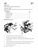
Page 15: ...rd 1 2 Interface Cable 1 3 Screw M3 x 6 2 4 Lock Screw 2 5 Washer 2 Installation Procedure 1 Remove the rear cover A Screws x 5 2 Remove the I F connector cover B Screws x1 3 Connect the I F board C a...

Page 16: ...ation a Part No VU5E 05 301 b Part No VU5E 05 404 c Part No VU5E 05 402 d Part No VU5E 10 002 Installation Time This installation should take 30 minutes excluding the time taken to install the video b...

Page 17: ...to hole marked A in Figure 2a screw in the 45 mm standoff D Into hole marked B in Figure 2a screw in the 45 mm standoff D Into hole marked C in Figure 2a screw in the 26mm standoff E NOTE 1 Tighten th...

Page 18: ...10 Attach five M3 x 6 mm screws on the mounting plate A then attach four M3 x 10mm male to female standoffs and one M3 x 10mm fe male to female standoff B NOTE There are three different size holes on...

Page 19: ...ep 7 12 Locate the UC5E main board C Part No VU5E 05 200 CAUTION THIS PART IS VERYSENSITIVE TO STATIC PLEASEENSURETHECORRECTANTISTATICPRECAUTIONS ARE TAKEN The RAM SIMM D should be on the left 13 Secu...

Page 20: ...ackageofVideoInterfaceKitType 10 Use the two M3 x 6mm screw from the package 16 Locate the 26 pin MPU cable B Part No VU5E 05 401 and connect the 26 pin twisted end C to the UC5E main board middle con...

Page 21: ...end to the outer connector on the UC5E main board The DB25 end is connected to the DB 25 cut out on the chassis of the main frame using the two M3 x 5mm jack posts supplied in the IF Kit Type 10 18 R...

Page 22: ...Locate the red and black power cable A Part No VU5E 05 300 Connect this cable CN114 on the MPU of the Digital Duplicator and J4 connector on the UC5E main board NOTE Secure the RED and BLACK power cab...

Page 23: ...22 Secure the keypad M3 x 10mm standoff C then mount the keypad PCB D onto the standoff C using a M3 screw 23 Connect the marguard cable into the flat connector on the Keypad PCB D NOTE 1 Make sure th...

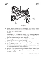
Page 24: ...olid sides facing each other 25 Mount the plate cover B onto the standoffs on the UC5E main board and secure with four M3 screws supplied 26 Plug in the power cord and switch on the Digital Duplicator...

Page 25: ...parts for this installation a Part No VU5E 06 300 b Part No VU5E 05 403 c Part No VU5E 05 405 d Part No VU5E 10 001 e Part No VU5E 05 401 Installation Time This installation should take 30 minutes ex...

Page 26: ...y 2004 4 Remove screws A B and C Keep them aside for later use 5 Locate the three M3 x 35mm standoffs D supplied Mount them into the holes NOTE Care must be taken not to damage the Digital Duplicator...

Page 27: ...3 x 6mm screws on the mounting plate A then attach four M3 x 10mm male to female standoffs to the outer screws and a M3 x 100mm female to female standoff to the middle screw NOTE There are three diffe...

Page 28: ...m standoff and screw it through the mounting plate into the standoff C 10 Locate the UC5E Main Board Part No VU5E 05 200 and secure it by screwing in a M3 x 6mm screw D CAUTION THIS PART IS VERY SENSI...

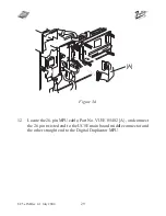
Page 29: ...v 2 1 July 2004 12 Locate the 26 pin MPU cable Part No VU5E 05 402 A and connect the 26 pin twisted end to the UC5E main board middle connector and the other straight end to the Digital Duplicator MPU...

Page 30: ...e outer ribbon plug on the Uc5E main board The DB25 end is connected to the DB25 cutout on the side chassis of the Digital Duplicator using the two M3 x 5mm jack posts B NOTE If a DB25 end cable is or...

Page 31: ...301 Connect the 4 pin side of the cable into the power plug on the UC5E main board Con nect the other end into connector CN702 of the Digital Duplicator NOTE Ensure the slack is taken up evenly on the...

Page 32: ...cable C part number VU5E 10 002 Connect the white pin connector end to the upright connector on the keypad PCB and the loose 4 x 2 pin connectors onto the UC5E main board NOTE Connectors 1 4 are sens...

Page 33: ...p right of the cover plate NOTE The button connectors have no polarity therefore they can be connected in either way 19 Plug in the power cord and switch the Digital Duplicator on 20 Press the T on th...

Page 34: ...wing parts for this installation a Part No VU5E 05 300 b Part No VU5E 05 403 c Part No VU5E 05 404 d Part No VU5E 10 002 e Part No VU5E 05 401 f Part No VU5E 05 301 InstallationTime Thisinstallationsh...

Page 35: ...gthepowercord 2 RemovetheUC5Eandancillaryitemsfromthebox 3 RemovetherearcoveroftheDigitalDuplicator 4 Install the interface board A 2 screws 5 Locate the cable B and connect the 26 pin straight end to...

Page 36: ...Locate the mounting plate E Orientate the plate correctly as shown 8 Attach five M3 x 6mm screws F on the mounting plate then attach four M3 x 10mm male to female standoffs G and one M3 x 10mm standof...

Page 37: ...wer cable I 10 Placetheassembledmountingplate J ontothestandoffsonthechassisand secure using the three M4 screws K 11 Install the UC5E main board L 12 InstallfourM3x25mmfemaletofemalestandoffs M NOTE...

Page 38: ...main board used in step 5 14 Connect the power cable P to main board 15 Connect the 26 pin ribbon cable end to outer connector on the main board The DB25 end is connected to the DB25 cut out on the c...

Page 39: ...Locatethe8pinribboncable S Connectthewhitepinconnectorontothe keypad PCB and the 4 x 2 pin connectors onto the main board NOTE Connectors 1 and 4 are sensitive to polarity Tlhese connectors should be...

Page 40: ...UC5e IM Rev 2 1 July 2004 18 Attach the UC5E front cover T and stick the marguard LED and button assembly U onto the outside bottom of the cover plate 19 ReinstalltherearcoveroftheDigitalDuplicator T...

Page 41: ...crew driver c Antistatic equipment Discard the following parts for this installation a Part No VU5E 05 300 b Part No VU5E 05 403 c Part No VU5E 05 404 d Part No VU5E 10 002 e Part No VU5E 05 401 f Par...

Page 42: ...ch and unplug the power cord 2 Remove your UC5E and ancillary items from the box 3 Remove the rear cover of the Digital Duplicator 4 Install the video I F board A from the package of Interface Cable T...

Page 43: ...U 7 Locate the mounting plate E part number VU5E05408 Orientate the plate correctly as shown 8 Attach five M3 x 6mm screws on the mounting plate E then attach four M3 x 10mm male to female standoffs t...

Page 44: ...standoff and screw it through the mounting plate into the standoff C 11 Locate the UC5E main board part number VU5E05002 and secure it by screwing in a M3 x 6mm screw D CAUTION 1 This part is very se...

Page 45: ...bbon PCB to cover cable C part number VU5E05410 and connect the 26 pin ribbon cable end to the outer rib bon plug on the UC5E main board The DB25 end is connected to the DB25 cutout on the side chassi...

Page 46: ...5E05301 Connect the 4 pin side of the cable into the power plug on the UC5E main board Connect the other end into connector CN702 of the Digital Duplicator NOTE Ensure the slack is taken up evenly on...

Page 47: ...ribbon cable C part number VU5E10002 Connect the white pin connector end to the upright connector on the deypad PCB and the loose 4 x 2 pin connectors onto the UC5E main board NOTE Connectors 1 4 are...

Page 48: ...of the cover plate NOTE The button connectors have no polarity therfore they can be con nected in either way 20 Plug in the power cord and switch the Digital Duiplicator on 21 Press the T on the marg...

Page 49: ...c Part No VU5E 05 403 d Part No VU5E 05 404 e Part No VU5E 10 002 Installation Time This installation should take 30 minutes excluding the time taken to install the video board 1 Turn off the main swi...

Page 50: ...e are three different size holes on the mounting plate A Use 5 of the 6 small tapped holes and the other holes are not used 7 Place the assembled mounting plate A onto standoffs on the chassis and sec...

Page 51: ...sted end C to the UC5E Main Board middle connector and the traight end to the interface board 11 Locate the 26 pin to 25 pin ribbon PCB to cover cable A Part No VU5E05410 and connect the 26pin ribbon...

Page 52: ...secure with a M3 x 6mm screw B supplied 14 Locate the 8 pin ribbon cable C Part No VU5E10001 Connect the white pin connector end to the upright connector on the keypad PCB and the loose 4 x 2 pin con...

Page 53: ...side tip right of the cover plate NOTE The button connector has no polarity therefore they can be con nected in either way 17 Plug in the power cord and switch the Digital Duplicator on 18 Press the T...

Page 54: ...ad screw driver c Antistatic equipment Discard the following parts for this installation a Part No VU5E 05 300 b Part No VU5E 05 403 c Part No VU5E 05 404 d Part No VU5E 10 002 e Part No VU5E 05 401 f...

Page 55: ...ensecure intotheholesintherearpaneloftheDigitalDuplicator 1 Turnoffthemainswitchandunplugthepowercord 2 RemovetheUC5Eandancillaryitemsfromthebox 3 RemovetherearcoveroftheDigitalDuplicator 4 Install th...

Page 56: ...F Orientate the plate correctly as shown 8 Attach five M3 x 6mm screws G on the mounting plate then attach four M3x10mmmaletofemalestandoffs H andoneM3x10mmstandoff I Note Therearethreedifferentsizeh...

Page 57: ...wer cable I 10 Placetheassembledmountingplate J ontothestandoffsonthechassisand secure using the three M4 screws K 11 Install the UC5E main board L 12 InstallfourM3x25mmfemaletofemalestandoffs M NOTE...

Page 58: ...main board used in step 5 14 Connect the power cable P to main board 15 Connect the 26 pin ribbon cable end to outer connector on the main board The DB25 end is connected to the DB25 cut out on the c...

Page 59: ...Locatethe8pinribboncable S Connectthewhitepinconnectorontothe keypad PCB and the 4 x 2 pin connectors onto the main board NOTE Connectors 1 and 4 are sensitive to polarity Tlhese connectors should be...

Page 60: ...UC5e IM Rev 2 1 July 2004 18 Attach the UC5E front cover T and stick the marguard LED and button assembly U onto the outside bottom of the cover plate 19 ReinstalltherearcoveroftheDigitalDuplicator T...

Page 61: ...ard LED and button assembly on the Model C235 remove the small rectangular panel on the rear cover of the Digital Dupli cator After a short delay a test page should be printed The test page should loo...

Page 62: ...l for name and position Thetablebelowexplainsthedifferentstatusindications T Indicator Display Meaning Flashes On after the UC5Einitialising thelightwillflashUC5Eis turned on once when switched ON and...

Page 63: ...et to ECP mode Problem Print jobs download to the UC5E but the Digital Dupli cator does not create a master Try the following a Press the Digital Duplicator on line key Some du plicators do not suppor...

Page 64: ...can send a description of the error to the ZipRip web site Please include all details such as PC specifica tion Operating System Application and version being used as well as a de tailed account of t...

Reviews: