13
UC5e IM Rev 2-1 July 2004
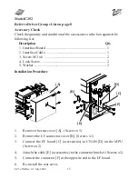
Model C238 and C247
Refer to Driver Groups List on page 8.
1. Remove the rear covers [A] [B] (8 screws).
2. Remove the I/F connector cover [C] (2 screws).
3. Install the I/F board [D] (accessories) in CN117 [E] on the MPU (2 screws).
4. Attach the cable [F] (accessories) to the connector bracket (2 screws) and
clamp the cable (6 clamps).
5. Connect the connector [G] at the opposite end to the I/F board.
6. Re-install the rear covers.


